Product overview
CP39xx-14xx-0010
11
Version: 1.1
3.2
Interface description
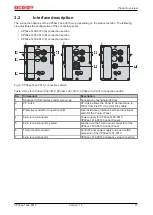
The connection options of the CP39xx-14xx-0010 vary, depending on the product version. The following
view illustrates the configuration of the connector panels.
• CP39xx-1400-0010 (A) connection section
• CP39xx-1401-0010 (B) connection section
• CP39xx-1414-0010 (C) connection section
1
2
3
4
5
6
7
8
9
10
11
12
13
14
15
16
17
18
19
B
A
C
1
4
5
6
7
2
3
Fig. 2: CP39xx-14xx-0010_connection section
Table 2: Key for CP39xx-1400-0010, CP39xx-1401-0010, CP39xx-1414-0010 connection section
No.
Component
Description
1
Single-port USB interface under screw cap
Connection of peripheral devices
2
CP-Link 4
CP-Link 4 allows the Panel to be located up to
100 m from the PC via a CP-Link 4 cable
3
Protective conductor connection (PE)
Low-resistance protective earth and functional
earth for the Control Panel
4
4-pin round connector
Power supply for CP39xx-1400-0010,
CP39xx-1414-0010 Control Panels
5
4-pin round connector, sealed
Function via the 19-pin round connector of the
CP39xx-1400-0010 Control Panel
6
19-pin round connector
Control Panel power supply and push button
extension of the CP39xx-1401-0010
7
4-pin round connector
CP39xx-1414-0010 emergency stop connection


