background image

Maintenance

CP39xx-14xx-0010

45

Version: 1.1

6

Maintenance

Maintenance measures increase the efficiency of the device by ensuring long-term functionality. Cleaning
the device contributes to this.

Defective pixels in the TFT display are production-related and are not grounds for complaint.

Cleaning

NOTE

Unsuitable cleaning agents

The use of unsuitable cleaning agents can damage the device.

• The Control Panel should only be cleaned as specified.

It is essential to observe the following aspects when cleaning the Control Panel:

• Make sure that no dust gets into the device.

• Use a soft, damp cloth to clean the Control Panel

• Do not use any aggressive cleaning materials, thinners, scouring material or hard objects that could

cause scratches.

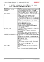
For further information please refer to chapter 9 

Chemical resistance of stainless steel panel with flush-

mounted touch screen [

}

 50]

Cleaning the front screen

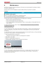
You can clean the front screen of the Control Panel during operation. In order to avoid inadvertent touch
entries when doing this, you must first set the device to "Cleaning Mode" with the help of the Beckhoff
Control Tool.

The Beckhoff Control Tool does not start automatically when the connected PC starts up. Proceed as follows
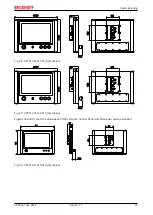
to activate the "Cleaning Mode" of the Beckhoff Control Tool:

1. Click the Beckhoff Control Tool to start it.

ð

When the tool is started, a small sun symbol appears in the taskbar.

2. Right-click the sun symbol.

3. Select the "Cleaning Mode" (see Fig. 46).

ð

"Cleaning Mode" is activated. You can now clean the front panel.

Fig. 46: CP39xx-14xx-0010_cleaning mode selection

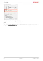
You can set the duration for which the Panel should remain in Cleaning mode. The period can be set
between 5 and 120 seconds. Right-click the sun symbol again and click "Options". Now select the
appropriate period (see fig. 42).

Summary of Contents for CP39-14-0010 Series

Page 1: ...Manual EN CP39xx 14xx 0010 Stainless steel multi touch Control Panel with CP Link 4 10 12 2021 Version 1 1...

Page 2: ......

Page 3: ...18 3 7 Connecting cable 19 3 8 Optional transmitter box CU8802 000x CU8803 000x 22 3 8 1 CU8802 000x for CP39xx 14xx 0010 22 3 8 2 CU8803 000x for CP39xx 14xx 0010 23 4 Commissioning 24 4 1 Transport...

Page 4: ...Table of contents CP39xx 14xx 0010 4 Version 1 1...

Page 5: ...onfigurations depicted may deviate from the standard Trademarks Beckhoff TwinCAT TwinCAT BSD TC BSD EtherCAT EtherCAT G EtherCAT G10 EtherCAT P Safety over EtherCAT TwinSAFE XFC XTS and XPlanar are re...

Page 6: ...rning of damage to property NOTE Disregarding the notice may lead to damage to property 2 2 Intended use The Control Panels of the CP39xx 14xx 00x0 series in stainless steel design are control and ope...

Page 7: ...cable with a fuse with a max rating of 16 A The fuse serves to protect the supply line in the event of a short circuit In case of fire extinguish the device with powder or nitrogen 2 4 Operator s obl...

Page 8: ...ainless steel surface Minimized clearance thanks to optimized housing design The design facilitates draining of spilled liquids in order to prevent adhesion of contaminants Sealing materials provide p...

Page 9: ...xx 0010 9 Version 1 1 Push button extension The following Control Panels can be ordered with push button extension ex works CP3913 1401 0010 CP3913 1414 0010 CP3916 1401 0010 CP3916 1414 0010 CP3918 1...

Page 10: ...0_configuration Table 1 Key for CP39xx 14xx 0010 configuration No Component Description 1 Mounting arm tube Mounting arm tube for installation from below or above 2 Optional RFID RFID integrated in th...

Page 11: ...x 1414 0010 connection section No Component Description 1 Single port USB interface under screw cap Connection of peripheral devices 2 CP Link 4 CP Link 4 allows the Panel to be located up to 100 m fr...

Page 12: ...voltage socket Pin Signal 1 24 V DC 2 GND 3 GND 4 24 V DC Due to the dual connection maximum wire cross sections of 4 x 0 75 mm2 can be accommodated For long supply lines use 4 x 0 75 mm2 cables to a...

Page 13: ...1401 0010_CP39xx 1414 0010_CP Link 4 Table 4 Pin assignment of the CP Link 4 socket Pin Signal 1 CP Link4_0P 2 CP Link4_0N 3 CP Link4_1P 4 CP Link4_1N 5 CP Link4_3P 6 CP Link4_3N 7 CP Link4_2N 8 CP L...

Page 14: ...CU8802 000x the Industrial PC is connected to the transmitter box via USB and DP DVI The transmitter box is then connected to the Control Panel via the CP Link 4 connection of the transmitter box usin...

Page 15: ...4 cable With this box USB DP DVI and power supply can be transmitted together via the cable One Cable Display Link No additional power supply is required for the CP39xx 14xx 0010 Figure 7 shows the wi...

Page 16: ...eak contact 2 5 Short stroke key S2 make contact 6 GND 7 Short stroke key S2 make contact 8 LED S2 green 9 Short stroke key S3 make contact 10 Short stroke key S3 make contact 11 LED S3 red 12 PE 13 S...

Page 17: ...RFID reader in the push button extension The following ordering option is available for this purpose Table 9 RFID reader ordering option Options Description C9900 E295 RFID reader for ISO14443 A B IS...

Page 18: ...me plate Key for CP39xx 14xx 0010 name plate No Description 1 Device name 2 Serial number BTN 3 Date of manufacture 4 Display 5 Touch screen 6 24 VDC power supply NEC class 2 7 FCC approval 8 Symbols...

Page 19: ...anel drag chain suitable with 4 pin round connector 10 m consisting of Power cable 2x0 75 mm conforming to UL cores color coded Side A Round 4 pin socket Side B not used C9900 K744 Power cable for Con...

Page 20: ...end open C9900 K619 Signal and power supply cable for push button extension drag chain suitable length 10 m 3x1mm 16x0 34mm pre assembled M23 socket IP65 screwable 19 core second end open C9900 K620...

Page 21: ...ne end with IP 65 connector C9900 K661 RJ 45 Cat 6A connection cable 90 m one end with IP 65 connector C9900 K662 RJ 45 Cat 6A connection cable 100 m one end with IP 65 connector C9900 K724 Connection...

Page 22: ...put for power supply of the CU8802 transmitter box Protection class IP 20 Operating temperature range 0 55 C Dimensions W x H x D 45 x 100 x 80 mm 1 m USB connection cable 1 m DVI connection cable Tab...

Page 23: ...3 Transmitter Box and the Control Panel Protection class IP 20 Table 18 CP Link 4 extender CU8803 0001 Accessories Description CU8803 0001 CP Link 4 Extender Tx for connecting a Control Panel with CP...

Page 24: ...a 49 Despite the robust design of the unit the components are sensitive to strong vibrations and impacts During transport the device must therefore be protected from mechanical stress Appropriate pack...

Page 25: ...nting arm installation from above or below Single part not mounted A separate tube holder is required for mounting C9900 M735 holder with welded on tube or C9900 M736 tube holder Before you can attach...

Page 26: ...addition an optional tilt adapter can be customer mounted on the Control Panel This option allows the Control Panel to be tilted by 10 Table 21 Tilt adapter ordering option Order identifier Execution...

Page 27: ...h the PTFE paste supplied section C A B C Fig 18 CP39xx 14xx 0010_mounting arm adapter installation 4 Use the bolt plates provided for temporary mounting section D 5 Use the M5 screws provided to fast...

Page 28: ...rew with the PTFE paste supplied section C A B C Fig 20 CP39xx 14xx 0010_installation of mounting arm adapter with tilt adapter 4 Release the four M5 screws of the connection plate section D 5 Positio...

Page 29: ...of the side to the Control Panel section I H I Fig 23 CP39xx 14xx 0010_installation of mounting arm adapter with tilt adapter 10 Screw the side covers back onto the mounting arm adapter A tightening t...

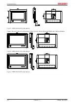
Page 30: ...g 25 CP3913 1400 0010_dimensions Figure 26 shows the dimensions of the 15 6 inch Control Panel 465 275 9 41 77 113 138 Fig 26 CP3916 1400 0010_dimensions Figure 27 shows the dimensions of the 18 5 inc...

Page 31: ...3 138 Fig 28 CP3913 1401 0010_dimensions 377 7 293 1 41 77 33 1 113 138 Fig 29 CP3913 1414 0010_dimensions Figures 30 and 31 show the dimensions of the 15 6 inch Control Panel with fitted push button...

Page 32: ...113 Fig 31 CP3916 1414 0010_dimensions Figures 32 and 33 show the dimensions of the 18 5 inch Control Panel with fitted push button extension 531 41 77 33 1 368 6 138 113 Fig 32 CP3918 1401 0010_dimen...

Page 33: ...the power supply An external power supply unit is required to supply 24 V DC 15 20 for operating the device Connect the Control Panel according to EN 60204 1 2006 PELV Protective Extra Low Voltage The...

Page 34: ...14xx 0010 34 Version 1 1 4 3 1 Circuit diagrams You can use the following circuit diagrams to plan your wiring in advance In addition you will receive a circuit diagram for your device Fig 34 CP39xx...

Page 35: ...Commissioning CP39xx 14xx 0010 35 Version 1 1 Fig 35 CP39xx 1414 0010_circuit diagram...

Page 36: ...ing the PE protective earth you establish the low resistance protective earthing of the Control Panel and thus avoid dangerous touch voltages EMC NOTE Hardware damage due to electromagnetic interferen...

Page 37: ...mm2 can be used for connecting the power supply For long supply lines use 4 x 0 75 mm2 cables to achieve a low voltage drop on the supply line There should be at least 22 V at the voltage connector o...

Page 38: ...Commissioning CP39xx 14xx 0010 38 Version 1 1 All data for the power consumption can be found in chapter 8 Technical data 49...

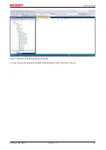
Page 39: ...alization PC via USB Follow the steps below to connect the push button extension in the TwinCAT System Manager Figs 37 to 41 1 Click at the top in the menu on File New Project and create a new TwinCAT...

Page 40: ...firm the request with Yes in order to scan for boxes Fig 40 TwinCAT_scan boxes 6 Confirm the request whether to enable FreeRun with Yes The device is inserted as a box in the tree view and displayed w...

Page 41: ...Commissioning CP39xx 14xx 0010 41 Version 1 1 Fig 41 TwinCAT_renaming terms and channels You can rename the individual channels of the respective terms as shown in Fig 41...

Page 42: ...ply to the CU880x transmitter box before disconnecting the CP Link 4 connec tion Before removing the Control Panel you must follow the steps below 1 Shut down the Control Panel 2 Disconnect the Contro...

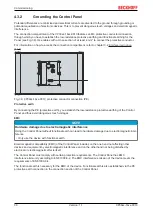
Page 43: ...f the two side covers section A 2 Release the set screw section B 3 Pull the Control Panel with the mounting arm adapter off the mounting arm tube section C A C B Fig 42 CP39xx 14xx 0010_mounting arm...

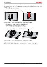
Page 44: ...Fig 44 CP39xx 14xx 0010_removing the mounting arm adapter with tilt adapter 3 Remove the four M5 screws of the connection plate section C 4 Release the six M5 screws on the tilt adapter section D 5 N...

Page 45: ...resistance of stainless steel panel with flush mounted touch screen 50 Cleaning the front screen You can clean the front screen of the Control Panel during operation In order to avoid inadvertent touc...

Page 46: ...x 0010 46 Version 1 1 Fig 47 CP39xx 14xx 0010_cleaning mode configuration Repair Only the manufacturer may repair the device If a repair should be necessary contact Beckhoff Service see Chapter 10 1 S...

Page 47: ...f they are operated under certain conditions such as more demanding ambient conditions during operation or during storage or if they are out of service for long periods of storage Beckhoff therefore r...

Page 48: ...missing functional earth of the device Establish functional earth Poor or missing ground connection of the user User must stand on the floor with normal shoes USB error during access with TwinCAT via...

Page 49: ...B10 value 65 000 cycles Switching elements emergency stop 1 20 126 504 9000 RAFI Rafix FS 2 break contacts Service life 1 000 000 cycles at 10 mA 24 VDC B10 value 1 300 000 cycles at 10 mA 24 VDC Sho...

Page 50: ...potassium hydroxide 30 paraffin oil castor oil pure turpentine isopropanol hexanol diacetone alcohol turpentine mineral oils cutting oil linseed oil unleaded petrol diesel oil petroleum benzine white...

Page 51: ...eckhoff Support Support offers you comprehensive technical assistance helping you not only with the application of individual Beckhoff products but also with other wide ranging services Support design...

Page 52: ...Statement This device was tested and complies with the limits for a digital device of class A according part 15 of the FCC regulations These limits are designed to provide adequate protection against...

Page 53: ......

Page 54: ...Beckhoff Automation GmbH Co KG H lshorstweg 20 33415 Verl Germany Phone 49 5246 9630 info beckhoff com www beckhoff com More Information www beckhoff com cp39xx 1400 0010...

Reviews: