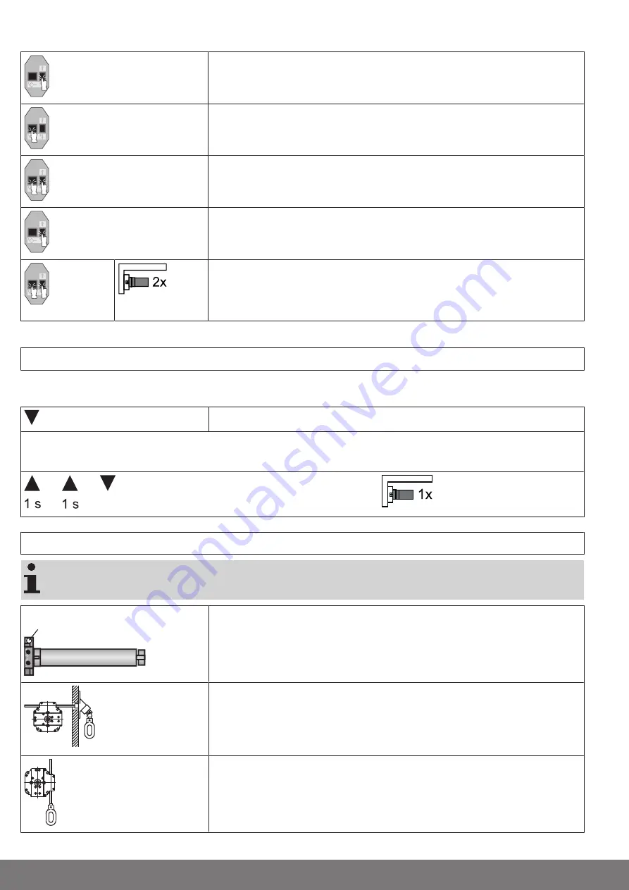
Deleting both limit positions
Open/close the shading solution to a point between the limit positions.
Press the programming button and keep it pressed.
Then press down the travel button and keep it pressed.
Now release the programming button, but continue to keep the travel button pressed.
Next press the programming button again.
▻
The tubular drive acknowledges.
►
Both limit positions are deleted.
Additional function offset lower limit position
The lower limit position can be advanced in 20° steps up to 60°. After 60° the forward displacement starts again at 0°.
Proceed as follows:
Move to the lower limit position.
Carry out the following sequence without interruption between the individual drive commands.
▻
The tubular drive confirms.
until STOP and hold until
Using the crank handle
For problem-free assembly, use mechanical and electrical accessories made by the drive
manufacturer which have been tested and which are suitable for use with these drives.
For 7 mm hexagonal tube
and 8 mm square tube
The crank handle is to be used only in the event of a power failure. It must be ensured
that the limit positions are not overrun. After using the crank handle, the limit posi-
tions must be referenced again. To do this, move in the opposite direction to the
per-
manent stop
to reference the limit positions again.
Crank handle for closed models
The crank handle for closed models can be used with roller shutters either with or
without a roll-up system. The square bar is fixed to the shutter box. Here, it is import-
ant to ensure that the bar is mounted parallel to the guide in the crank handle hous-
ing.
Crank handle for open models
These crank handles can be used with roller shutters without roll-up systems. Insert
the square bar into the guide in the crank handle housing and secure axially using a
retaining washer or two set screws.
14 - en


