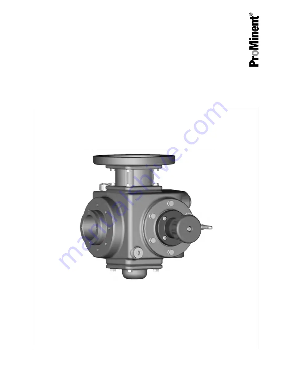
background image

Drive unit
Orlita

®

 Evolution

Operating instructions

These operating instructions form part of an operating manual and are only valid if used in conjunction with the documents

in this operating manual.

EN

983748

BA ORL 008 06/16 EN

Please carefully read these operating instructions before use. · Do not discard.

The operator shall be liable for any damage caused by installation or operating errors.

The latest version of the operating instructions are available on our homepage.

Summary of Contents for Orlita EF1a

Page 1: ...sed in conjunction with the documents in this operating manual EN 983748 BA ORL 008 06 16 EN Please carefully read these operating instructions before use Do not discard The operator shall be liable f...

Page 2: ...20 5 1 Tests Prior to Start Up of the Pump 22 5 2 Testing Directly After the Pump has Started Up 24 5 3 Testing 0 5 to 1 Hour After the Pump has Started 25 5 4 Bleeding the Diaphragm Holder 25 6 Maint...

Page 3: ...ng hot surface Warning danger zone n Only operate the pump in premises at risk from explosion with the appropriate nameplate for pumps for use in areas at risk of explosion in accordance with the Euro...

Page 4: ...respective service lives Task Qualification Transport Qualified personnel Storage unpacking Instructed person Assembly Technical personnel Service Planning the hydraulic installation Qualified personn...

Page 5: ...protection qualification should be specifically trained for the work area in which he is employed and be familiar with the relevant standards and regulations The electrical technician with an addition...

Page 6: ...very country and every type of application nor to being unconditionally up to date WARNING Only use ATEX pumps in areas at risk from explosion Note the relevant regulations for the installation and op...

Page 7: ...latest safety data sheet for the chemicals equipment to be used with the system from the supplier Based on the information provided in the data sheets concerning health and safety water and environmen...

Page 8: ...the operating instructions and if the mains cable remains disconnected from the mains voltage Make sure that all protective equipment is refitted during operation The operator must be able to n Perfor...

Page 9: ...l or an actuator optional or control drive optional The pump s stroke rate can be changed by a frequency converter optional if required One or more add on drive units can be attached to the main drive...

Page 10: ...upling operating instructions WARNING This is EX relevant in areas at risk from explo sion With a claw coupling Make sure that the claw on the motor shaft is fixed at the correct height see Fig Fig 1...

Page 11: ...4 1a 40 0 75 kW F200 24 1a 40 0 55 kW F160 19 1b 41 0 35 kW F160 19 1b 41 EF2a Motor Motor flange Rotex Q 1 5 kW F200 24 1a 40 1 1 kW F200 24 1a 40 0 75 kW F200 24 1a 40 0 55 kW F200 24 1a 40 EF3a Mot...

Page 12: ...In an area at risk from explo sion it could trigger an explosion Maintain sufficient clearance between the air intake opening and the walls The distance should be greater than 1 4 of the diameter of...

Page 13: ...as the oil inspec tion windows are easily accessible Make sure that there is sufficient room to carry out an oil change or perform other maintenance work and repairs 1 Discharge valve 2 Dosing head 3...

Page 14: ...Protect the pump from lightening Install a guard if the pump is exposed to direct sunlight or another heat source Lightning protection Direct sunlight Assembly 14...

Page 15: ...areas at risk from explosion Electrically wire all electrical units cleanly and per manently to an electrically clean earthing point e g with an earthing bar on your system Electrically wire the earth...

Page 16: ...isolating option WARNING Danger of electric shock This pump is equipped with a protective earth con ductor to reduce the risk arising from an electric shock Connect the PE conductor to earth with a c...

Page 17: ...nst overloading Fuses do not provide motor protection CAUTION Pump can be damaged The pump can be damaged if the motor drives the pump in the wrong direction When connecting the motor pay attention to...

Page 18: ...e All pumps ordered with an electric diaphragm rupture sensor need to be electrically installed Electrically wire the enclosed diaphragm rupture sensor to a suitable monitoring device CAUTION Addition...

Page 19: ...d installation cleanly and permanently to an electrically clean earthing point e g with an earthing bar on site see earthing dia grams in the appendix Connect the partial potential equalisation points...

Page 20: ...r potential equalisation before you approach any pump equipment that could be at a different electrical potential such as pipes or tools WARNING Danger of fire with flammable feed chemicals Combustibl...

Page 21: ...ectric shock There is still the risk of an electric shock on conducting parts of the frequency control unit e g frequency con verter the motor and the cables even after the mains voltage has been swit...

Page 22: ...Trigger the electric diaphragm rupture sensor see Operating Instructions for Electric Diaphragm Rupture Sensor and thus check the reaction of the monitoring unit and or the pump CAUTION Only restart t...

Page 23: ...losing screws on the oil filler neck with the vent screws supplied Slight oil marks on the pump do not indicate leaks with a new product Remove any oil stains and note their position Set the stroke le...

Page 24: ...e motor flange 1 Unscrew the screw from the control opening on the motor flange 2 Push a long thin piece of cardboard a little way into the opening with the motor running 3 Remove the cardboard from t...

Page 25: ...dipstick screw in the vent screw with the measuring dipstick to do so 5 4 Bleeding the Diaphragm Holder Bleed the hydraulics once to start up 1 Set a stroke length of 0 mm 2 Unscrew the oil inspectio...

Page 26: ...6 Maintenance refer to the Operating Instructions for the Liquid Ends Orlita Evolution Maintenance 26...

Page 27: ...7 Carrying out repairs refer to the Operating Instructions for the Liquid Ends Orlita Evolution Carrying out repairs 27...

Page 28: ...nected Check that the supply cables are de energised WARNING Risk of injury from the fan impeller The fan impeller beneath motor s fan cowling can cause severe injuries while it is turning The pump mu...

Page 29: ...fault Cause Remedy Personnel Gear motor makes loud noises Bearing damage on the motor shaft Replace bearings or motor Service Overload Monitor the process parameters Qualified employee Monitor the pro...

Page 30: ...9 Decommissioning and Disposal refer to the Operating Instructions for the Liquid Ends Orlita Evolution Decommissioning and Disposal 30...

Page 31: ...17 F Fastening 13 Frequency converter 18 Functional description 9 H Hydraulic oil flow 24 I Information in the event of an emergency 7 Installation Electrical 15 Intended use 3 L Lightning protection...

Page 32: ...Heidelberg 3 en_GB 2015 ProMinent GmbH Im Schuhmachergewann 5 11 69123 Heidelberg Germany Germany Telephone 49 6221 842 0 Fax 49 6221 842 419 Email info prominent com Internet www prominent com...

Reviews: