background image

19

9 INCH CHIPPER

ENGLISH

OPERATION

Bar safety system has been activated. 

To re-engage the 

feed roller safety system after the Knee Bar safety 

system has been activated, the operator must press 

and hold the Knee bar Reset button for two seconds.
Any time the Knee Bar safety system is activated, 

carefully check that the infeed chute and feed roller 

are clear and it is safe to continue chipping before 

resetting the Knee Bar safety system.

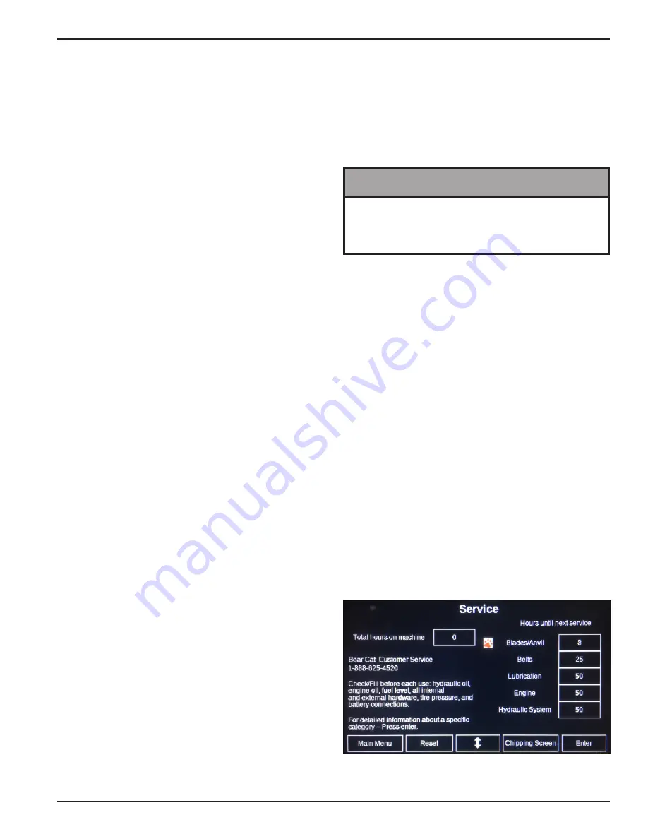
4.7.3 HOURS/SERVICE REMINDERS

The Hours/Service Reminders screen is shown in 

Figure 4.6.
The Total hours on the chipper are shown in the upper left 

corner of the screen. The total hours are based on “Key 

On” time and cannot be reset.
The service reminders on the right hand side of the screen 

are all count down timers. They all show the time until 

the next service is required in each category. Additional 

information for each category can be found by moving the 

cursor next to a category with the Navigation Button and 

pressing Enter.


Blades/Anvil –

 Hours are based on the time the 

feed roller is in Forward since that is the only time the 

blades can actually chip wood.


Belts –

 Hours are based on “Key On” time.


Lubrication –

 Hours are based on “Key On” time.


Engine –

 Hours are based on “Key On” time. The 

service interval is dependent on the model selected. 

(Does not apply to PTO driven models.)


Hydraulic System –

 Hours are based on “Key On” 

time. First service interval is at 50 hours; subsequent 

service intervals are at 200 hours.

Anytime the user leaves the Chipping Screen, the 

feed roller will automatically stop. The user will have to 

re-enter the Chipping Screen and press the Forward 

button again to resume chipping.

NOTE

Figure 4.6, Hours/Service Reminders

In the upper left hand corner of the screen is a reminder 

that the feed roller speed can be adjusted. The adjustment 

occurs at the control valve, the location of which varies by 

model. In general, the speed of the feed roller should be 

slower for large diameter material and faster for smaller 

diameter material. See chipper owner’s manual for 

detailed instructions.
Below the Feed Roller Speed image is an empty area of 

the  screen  that  will  flash  Check  blades/anvil  when  the 

chipper blades or anvil require service.
After servicing the blades and anvil, the service indicator 

will need to be reset. See Section 4.7.3 for information on 

resetting the service indicators.
The large indicator in the upper right hand corner and the 

text box below it will give one of four indications:


Flashing Green –

 The chipping rotor has not achieved 

enough RPM to begin chipping. It is not possible to 

engage the feed roller in the forward direction when 

the indicator is flashing green. The text box below the 

indicator will display “RPM Not Met.”


Solid Green –

 The chipping rotor has achieved 

sufficient RPM to begin chipping. The feed roller can 

now be engaged in the forward direction. The text 

box below the indicator will display “FORWARD,” 

“REVERSE,” or “STOP.”


Solid Red –

 The knee bar has been activated and the 

feed roller is now stopped. The text block below the 

indicator will display “Hold Knee Bar Reset.”
The Knee Bar functions as an emergency stop system 

for the feed roller to immediately stop the feed roller 

system. Occasionally, branches or limbs may contact 

the Knee Bar with enough force to activate the Knee 

Bar safety circuit. When this occurs the operator will 

need to reset the Knee Bar safety system with the 

“Knee Bar Reset” button to continue chipping. The 

“Knee Bar Reset” button will need to be held for two 

seconds to reset the system.

Carefully check to be certain the infeed chute and 

feed roller are clear and that it is safe to continue 

chipping before resetting the Knee Bar Reset.


Solid Yellow –

 There is a fault in the chipper control 

system. The text box below the indicator will display 

“Go to Diagnostic Screen.”

The buttons to the left and to the right of the Navigation 

Button are used to control the feed roller.
The Forward button starts the feed roller turning forward 

and feeds material into the chipper.
The Reverse button reverses the direction of the feed 

roller and will push the material back toward the operator.
The Stop button stops the feed roller.
The Knee Bar Reset button resets the controller so 

Forward and Reverse can be re-engaged after the Knee 

Summary of Contents for CH911DH

Page 1: ...ENGLISH ESPA OL FRAN AIS BEARCATPRODUCTS COM 888 625 4520 OWNER S MANUAL ENGLISH 1 1L DIESEL KUBOTA P N 78636 00 Revision 20220822 VIN Range 5VJAA0411NW006958 Current Companion to P N 78640 00...

Page 2: ...e parts manual for your machine is available at bearcatproducts com Product Support Find A Product Manual Your dealer will need to know the serial number of your machine to provide the most efficient...

Page 3: ...t of that work will not be paid under this warranty Crary Industries Inc does not warrant replacement components not manufactured or sold by Crary Industries Inc 1 This warranty applies only to parts...

Page 4: ...E CHIPPER 13 4 3 CHIPPER OPERATION GUIDELINES 15 4 4 SLOWING AND STOPPING THE CHIPPER ROTOR AND ENGINE 16 4 5 FEED ROLLER SPEED CONTROL 16 4 6 CHIPPER FEED CONTROLLER 16 4 7 USING THE DIGITAL DISPLAY...

Page 5: ...caught in the machine 6 Do not operate this machine if you are under the influence of alcohol medications or substances that can affect your vision balance or judgement Do not operate if tired or ill...

Page 6: ...king condition before starting the machine 17 Do not transport or move machine while it is operating or running 6 Therotorwillcontinuetorotateafterbeingdisengaged Shut off the machine and make sure al...

Page 7: ...reach an open flame or spark 5 Never store this machine with fuel in the fuel tank inside a building where fumes may be ignited by an open flame or spark Ignition sources can be hot water and space he...

Page 8: ...arranty See Section 1 10 for decal locations Familiarize yourself with all of the safety and operating decals on the machine and the associated hazards See the engine owner s manual or contact the eng...

Page 9: ...5 PN 32332 00 ENG FR 32341 00 ESP PORT 1 10 SAFETY DECAL LOCATIONS The numbers below correspond to the decals in Section 1 9 Make certain that all safety and operating decals on this machine are kept...

Page 10: ...ust the hitch pole to desired length and secure to frame by inserting the 1 6 hitch pole pin through the appropriate hole in hitch pole and hole in frame 3 Secure the hitch pole pin with lynch pin 4 A...

Page 11: ...on each side and two on the bottom Install clamp 7 for wire harness as shown in Figure 2 3 If feed roller is obstructing the top bolt holes it may be necessary to use the hydraulic jack to raise the f...

Page 12: ...terior of the extension tray using two 5 16 3 4 bolts 6 and one nylock nut 5 as shown in Figure 2 6 2 5 ATTACH DIGITAL DISPLAY CONTROLLER MOUNT ASSEMBLY 1 Remove the bolts 1 and nuts 2 attaching the d...

Page 13: ...2 8 10 13 Figure 2 8 Attach Discharge Tube 1 2 4 5 6 Keep nuts as tight as possible while allowing the discharge tube to freely turn NOTE Figure 2 7 Attach Clamp Ring and Spacer 1 2 3 4 5 5 Lubricate...

Page 14: ...he feed roller The machine was shipped with fluid as it was tested at the factory However check the fluid levels before initial operation and add if necessary The hydraulic pump requires premium hydra...

Page 15: ...erstanding how your machine works will help you achieve the best results when using your chipper The following descriptions define the features and controls of your machine REFER TO ENGINE OWNER S MAN...

Page 16: ...crease the speed of the feed roller Turning the knob counterclockwise will increase the speed of the feed roller 11 HITCH JACK Always have in UP position and clear from ground when towing When in use...

Page 17: ...ved Warning Alarm Icons Fail to Stop Note Fail to Stop could indicate a faulty oil pressure sensor If the engine is at rest check oil sensor wiring and configuration The controller has detected a cond...

Page 18: ...r the configured number of start attempts LowOilPressure The controller detects the engine oil pressure is low after the Safety On Timer expired High Coolant Temperature The controller detects the eng...

Page 19: ...doors before starting Do not operate in the vicinity of bystanders Make sure cutting chamber is empty before starting WARNING 4 Open the throttle slightly by turning throttle knob A counterclockwise a...

Page 20: ...to chip pieces of metal rock bottles cans or other foreign objects Never lean over the chipper chute to push objects into the cutting device Use a push stick or brush paddle Never use shovels or fork...

Page 21: ...TO PROPERLY SLOW DOWN AND STOP THE ROTOR AND ENGINE 1 With the belt still engaged unlock the throttle and SLOWLY turn clockwise until engine reaches slow idle speed 2 Allow the engine to run at slow...

Page 22: ...Controller Manual P N 78561 00 for more information on using the Diagnostics screen to help troubleshoot the chipper control system NOTE The Chipping Screen is accessible from any screen by pressing t...

Page 23: ...for detailed instructions Below the Feed Roller Speed image is an empty area of the screen that will flash Check blades anvil when the chipper blades or anvil require service After servicing the blade...

Page 24: ...nder the hitch and connect to towing vehicle 10 Connect the wire harness to the tow vehicle 11 Raise the jack stand and rotate 90 degrees 4 8 2 DETACHING 1 Unhook the safety chains from the towing veh...

Page 25: ...All internal and external nuts and bolts Check tightness Tire pressure Check Battery connections Check Chipper anvil Check clearance and re torque to 75 ft lbs 2 Chipper blades Check sharpness and re...

Page 26: ...edge is worn or has been re sharpened so that it no longer extends past the chipping slot see below 5 2 ROTOR LOCK Follow the steps below to install the rotor lock 1 There is a hole in the shaft cap t...

Page 27: ...er housing see Section 5 3 4 Remove rotor lock 30 Figure 5 2 Chipper Blade Surfaces 1 Open access cover to allow access to rotor see Section 5 3 Rotate the rotor so that the bolts holding the chipper...

Page 28: ...OTOR ANVIL SPACING GAUGE 1 16 1 8 Figure 5 5 Chipper Blade Anvil Clearance ROTOR HOUSING CHIPPING ANVIL SPACER FEED ROLLER HOUSING Figure 5 4 Chipping Anvil Location The chipping blades should clear t...

Page 29: ...e drive belt annually or after every 25 hours of operation whichever comes first If the belt is cracked worn frayed or stretched replace it Replace belt with original banded belt type only Do not use...

Page 30: ...cer on the rotor side Remove spacer from shaft 8 Remove the four 1 2 bolts on belt side bearing and take off the sensor bracket Remove bearing and discard 5 12 2 REMOVING FEED ROLLER SIDE BEARING 1 Li...

Page 31: ...t the fluid levels are filled However before starting the machine and every time the engine is started thereafter be sure to check the coolant level If the level is low add fluid Refer to the engine o...

Page 32: ...quent greasing Grease the following points every 50 100 hours of operating time Two bearings on the rotor shaft Two bearings on the hydraulic feed roller One bushing on the belt engagement pedal pivot...

Page 33: ...per has not reached chipping RPM upon initial startup Slowly increase RPM 1 2 second on 1 2 second off Chipper RPM dropped while chipping Feed roller will automatically pause to bring RPM back up RED...

Page 34: ...n too loose Adjust tensioner Replace belt if needed Machine chips poorly Dull chipper blades Flip sharpen or replace Drive belts loose or worn Inspect drive belts adjust or replace if needed Feeding m...

Page 35: ...rm that PTO is 540 RPM Knee bar sensor does not stop feed roller Knee bar linkage is not free to move Check knee bar linkage for full range of motion Harness connection or sensor failure Check harness...

Page 36: ...79 100 368 cm 201 cm 254 cm Overall weight 2470 lbs 1120 kg Max chipper capacity 9 diameter 22 9 cm diameter Chipper blades 4 reversible 5 4 0 5 4 reversible 12 7 cm 10 2 cm 1 3 cm Chipping anvil 9 4...

Page 37: ...es by 5 BOLT DIAMETER A BOLT TORQUE SAE 2 SAE 5 SAE 8 NM FT LB NM FT LB NM FT LB 1 4 7 5 5 5 11 8 16 12 5 16 15 11 23 17 34 25 3 8 27 20 41 30 61 45 7 16 41 30 68 50 95 70 1 2 68 50 102 75 149 110 9 1...

Page 38: ...CHIPPER SPECIFICATIONS 7 2 TEMPERATURE OPERATING WINDOW For the nearest Mobil lubricant supplier or technical information including lubricant information for severe arctic operating conditions call 80...

Page 39: ...1725 00 2 5 16 Coupler Kit 14519 00 PART NUMBER DESCRIPTION 14519 00 COUPLER 2 5 16 20 000 LB 14900 00 HITCH PINTLE RING 20 000 LB 33900 00 KEY DSE 71072 00 KIT CHIPPER ELECTRIC BRAKES 71725 00 KIT LO...

Page 40: ...ND 58078 For customer service or for your nearest Crary Bear Cat dealer call 888 625 4520 For International call 701 282 5520 BEARCATPRODUCTS COM 2021 Crary Bear Cat a subsidiary of ECHO Incorporated...

Reviews: