background image

BDDF00122 Issue 3

16/36

Alaris™ Gateway Workstation v1.3.x

Features of the Workstation

Adjustable Height Bag Hangers (where fitted)

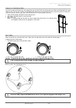
The 18 mm diameter adjustable height pole has been designed as a convenient means of securing the fluid bags onto the Workstation . 

The pole supports a maximum load to 3 kg . The pole is held securely by a clamp and a slip catch . This gives additional flexibility when 

selecting the required height of the fluid bags . To operate the clamp:

1 .  Grip the handle at the lower end of the pole and carefully loosen the hand wheel .

3b

1

2

4

3

2 .  Apply an upward pressure to the pole handle, this will release the locking lever and allow 

the pole to move freely .

3 .  Changing the bag hanger height:

a)  To increase the bag hanger height: Continue pushing the pole upward to the required 

height . Once set, release the upward pressure on the pole, re-engaging the locking lever .

b)  To reduce the bag hanger height: Hold the locking lever in the released position and 

adjust the pole downward to the required height . Release the locking lever and release 

the upward pressure on the pole, re-engaging the locking lever .

4 .  Tighten the hand wheel to securely lock the pole into position .

To reduce the potential risk for nuisance alarms, the fluid bag should be placed at the height recommended in the 

specific Pump Directions For Use, bag hanger poles should be adjusted to the required height.
For Workstation configurations 80300UNSxx-235 and 80300UNSxx-035, use the bag hanger assembly PN 1000SP01414 

to secure fluid bags onto the Workstation.

Power Input

The Workstation is powered from the AC supply through a standard IEC AC connector . When connected to the AC supply the AC Power 

indicator is illuminated . Both the Live and Neutral lines of the main supply are protected using fuses carried in a double fuse holder 

located on the AC inlet connector .

Warning:   When connected to the AC supply, a three wire (Live, Neutral, Earth) supply must be used. If the integrity of the 

external protective conductor in the installation or its arrangement is in doubt, then the Workstation must not be 

used.

To isolate the Workstation from AC supply remove the AC connector from the source socket. The Workstation should 

be positioned to allow access for disconnecting the AC connector.

Battery Supply

The Workstation should normally be operated from the AC power supply . However, in the event of temporary loss of AC power, an 

internal power supply will provide 60 minutes of communications . AC power to the Pumps will be discontinued .

Warning:   AC Power should be re-applied as soon as possible as there will be no AC power supplied to the Pumps while the 

Workstation is running on the battery. 

The Battery indicator illuminates whenever the Workstation is running from the internal battery . When illuminated the Workstation is 

operating from internal battery; when flashing the battery power is low and auto power down is imminent . The battery is automatically 

charged whenever the Workstation is connected to the AC supply . As the Workstation is designed to operate from the AC power supply it 

will only power up when connected to the AC supply .

Caution:   In the event of a power loss, the Workstation with fully charged battery will emit an audible tone every 30 seconds 

for the first 14 minutes to alert operators, accompanied by a visual indicator. This audible tone and visual indicator 

will escalate to every 15 seconds after 14 minutes until the battery is fully depleted. These tones and indications 

should not be confused with the continuous alarm and LED notification that is initiated if the Workstation exhibits a 

fault condition.

If transfer of the Workstation is required, then prior to disconnecting from AC power supply the User must ensure 

there is sufficient battery power on each of the Pumps.

Summary of Contents for Alaris Gateway Workstation v1.3.x

Page 1: ...u Alaris Gateway Workstation v1 3 x Directions For Use en...

Page 2: ...to Infusion Pumps 17 Powering an auxiliary Workstation 17 System Notifications 18 System Fault Indication 19 Nurse Call Interface 19 Pump Alarm Location Beacon where fitted 20 Operating Precautions 2...

Page 3: ...t Interface where fitted 30 Auxiliary Interface 30 Product Specifications 31 Electrical 31 Battery 31 Environmental 31 Classification 31 Regulatory Compliance 31 Potential Equalisation Conductor 31 Pa...

Page 4: ...32 SN T 135070253 17 04 2014 This is an entry level Workstation with organization and central AC power supply functionality It does not support PDMS connectivity It may be used as an Auxiliary Worksta...

Page 5: ...h has an odd number and that the AC power Cable socket is at the front Note Please make sure to refer to the correct Workstation Directions For Use to familiarise with the specific Workstation version...

Page 6: ...tory alarms and warnings from software versions prior to 3 4 5 3RD EDITION ALARMS Low medium and high priority alarm tones in accordance with IEC 60601 1 8 2012 and IEC 60601 2 24 2012 Note The 3rd Ed...

Page 7: ...p with Plus Software 9002TIG03 v2 3 x Yes Yes Yes Yes Yes Yes Alaris GP Guardrails Volumetric Pump with Plus Software 9002TIG03 G v2 3 x Yes Yes Yes Yes Yes Yes Alaris VP Plus Guardrails Volumetric Pu...

Page 8: ...8002MED01 8002TIG01 v4 1 8 Yes Yes Yes Yes Alaris CC Syringe Pump with Plus Software MK4 8003MED01 8003TIG01 v4 1 8 Yes Yes Yes Yes Alaris GH Guardrails Syringe Pump with Plus Software MK4 8002MED01 G...

Page 9: ...Pump Alaris GW 800 Volumetric Pump Condition Alarm Location Beacon Behaviour Alarm Location Beacon Behaviour End of Infusion KVO enabled Amber Beacon in KVO Phase None for KVO Phase End of Infusion K...

Page 10: ...0300UNSxx where xx indicates the connectivity option The two or three numbers at the end of the SKU identifies the Workstation configuration see below for all available configurations Available Config...

Page 11: ...e can be obtained free of charge by contacting your local BD representative An estimated delivery time will be provided when the order is placed Conventions used in this manual BOLD Used for Display n...

Page 12: ...tion j j Battery Indicator When illuminated the Workstation is operating from internal battery when flashing the battery power is low and auto power down is imminent k k AC Power Indicator When illumi...

Page 13: ...onnector IP22 Protection against fingers or other object not greater than 80mm in length and 12mm in diameter Protection against water droplets deflected up to 15 from vertical Protected against acces...

Page 14: ...able Height Pole Slip Catch Pump Alarm Location Beacon Not fitted on 4 MDI Tile Horizontal Module Bag Supports w Alaris Gateway Workstation v1 3 IP22B Covered under Patents U S Pat 6 593 528 EP 150261...

Page 15: ...ion Configuration 80300UNSxx 235 shown mounted on an Alaris Trolley Infusion Line Tidies Bag Supports Trolley Bag Support Rail Mounting Rail Mounting Rail Mounting Rail Note Qualified Service Personne...

Page 16: ...ure the device 3 Refit rubber strip Note It is recommended that line tidies be used to organize the infusion lines this could reduce the risk of tangled infusion lines and tripping the user or patient...

Page 17: ...double fuse holder located on the AC inlet connector Warning When connected to the AC supply a three wire Live Neutral Earth supply must be used If the integrity of the external protective conductor...

Page 18: ...Pumps When the Workstation is initially switched on or when re connected to the AC whilst operating from the internal battery a small delay in the application of AC power will occur between each MDI...

Page 19: ...on Barcode Reader Barcode LED Primary Speaker Status See Barcode Reader Docking Pump Warning LED N A Status See Docking a Pump and Removing a Pump Nurse Call Nurse Call N A Nurse Call See Nurse Call P...

Page 20: ...FI signal is a continuous tone Nurse Call Interface A nurse call interface is provided which is activated whenever any Pump attached to the Workstation enters an alarm state and stops when the conditi...

Page 21: ...smatched Pump alarm location beacon behaviour when using Pumps with selectable alarm profiles Caution If the Pump Alarm Location Beacon fails to illuminate when the Workstation is switched on suspect...

Page 22: ...601 1 2 and ETSI EN 301 489 17 where applicable If however the Workstation interacts with other equipment measures should be taken to minimise the effects for instance by repositioning or relocation T...

Page 23: ...wing conditions occur with the Workstation remove it from service for inspection by Qualified Service Personnel dropped excessive moisture fluid spillage high humidity high temperature suspicion of da...

Page 24: ...ndle is in full working order before use Warning The pole clamp should be used to mount the Workstation on fixed poles overhead swing arm poles only Warning People of a weak disposition should not att...

Page 25: ...extinguished Verify the System Fault indicator illuminates briefly emits a series of beeps and is then extinguished 9 Nurse call test when connected Nurse call automatically activated Not applicable...

Page 26: ...once on the auxiliary Workstation to switch the auxiliary Workstation on Removing an Auxiliary Workstation If the primary Workstation cannot be switched off for whatever reason then the Pumps fitted...

Page 27: ...AC power and data communications once correctly located on the MDI tile InorderfortheWorkstationandPumptocommunicatecorrectly thePumpmustbeconfiguredtoIrDACommunication not RS232 Communication Please...

Page 28: ...llows the use of either fixed or dynamic network addressing of the Workstation Similarly a DNS client is provided Configuration of these client services is through the Workstation Web Browser User Int...

Page 29: ...atus of the reader All LEDs off The barcode reader is not receiving power or the barcode reader is in standby mode Steady Green The laser is active Steady Green Single Red Flash The barcode has been r...

Page 30: ...h BD supplied barcode reader only Workstation Connector Type Binder 09 0998 00 05 Cable Type N A Description 1 2 3 4 5 Pin 1 5V Pin 2 TxD Pin 3 GND Pin 4 RxD Pin 5 SENSE Serial RS232 Interface Connect...

Page 31: ...Features IEEE 802 11 a b g n Connects to any existing 2 4 or 5 GHz network Wi Fi Protected Access WPA WPA2 and WEP encryption Note If you are upgrading from legacy Workstation to Workstation version...

Page 32: ...Up to 16 hours to 95 charge time based on battery life cycle and an 11 Pump load Operating time 60 minutes Environmental Operating Transport and Storage Temperature 5 C 40 C 20 C 50 C Humidity 20 90...

Page 33: ...ibility Configuration1 Trolley Compatible 80083UN00 00 5 Alaris Trolley Compatible 80203UNS00 00 6 80300UNSxx 30 80300UNSxx 32 80300UNSxx 33 80300UNSxx 34 80300UNSxx 50 80300UNSxx 52 80300UNSxx 53 803...

Page 34: ...or identification of parts Inspect AC outlets communication connectors and the AC inlet for damage Perform electrical safety checks The complete unit leakage current must be measured If more than 500...

Page 35: ...excess fluid build up on the Workstation Do not use aggressive cleaning agents as these may damage the exterior surface of the Workstation Do not steam autoclave ethylene oxide sterilise or immerse t...

Page 36: ...to obtain login details Part Number Description 0000EL00889 AC Power Lead UK 0000EL00938 AC Power Lead European Accessories Part Number Description 1000SP00655 Rail Mounting Kit 1000SP00169 Pole Moun...

Page 37: ...39 0 55 303391 customer service italy bd com Magyarorsz g 36 1 488 0233 info cfn export bd com Nederland 31 0 20 582 94 20 info benelux bd com New Zealand Freephone 0800 572 468 NZ_customerservice bd...

Page 38: ...nt contains proprietary information of Becton Dickinson and Company or one of its affiliates and its receipt or possession does not convey any rights to reproduce its contents or to manufacture or sel...

Reviews: