Understanding the Display and Workstation
5 - 21
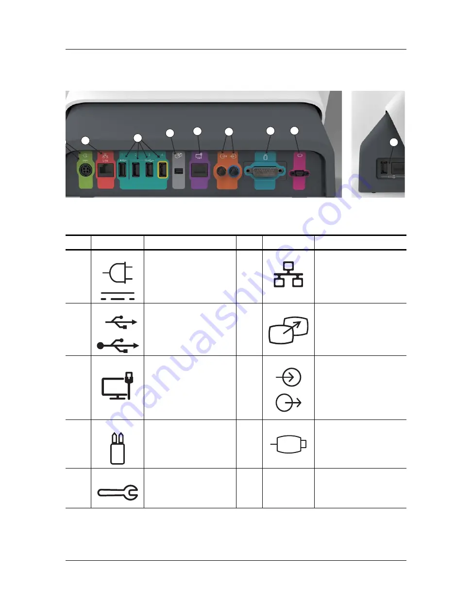
Figure 5 - 6: Workstation, Rear and Side Port View
5
8
9
10
11
6
7
12
Icon
Description
Icon
Description
4
Identifies power input and
supply connection.
5
Identifies computer network
connection.
6
Identifies USB connections.
Port 4, identified with yellow
outline, always remains on.
7
Identifies connection for
screen extension or transfer to
a second display. For Bayer
use only.
8
Identifies a connection not
applicable for MEDRAD
®
Stellant. Not for use with the
system.
9
Identifies input and output
connections not applicable for
MEDRAD
®
Stellant. Not for use
with the system.
10
Identifies injector head
connection.
11
Identifies handswitch
connection.
12
Identifies service ports. For
Bayer use only.
SS
Summary of Contents for Certegra
Page 2: ......
Page 4: ...MEDRAD Stellant CT Injection System with Certegra Workstation ii ...
Page 18: ...MEDRAD Stellant CT Injection System with Certegra Workstation 2 10 ...
Page 34: ...MEDRAD Stellant CT Injection System with Certegra Workstation 6 26 ...
Page 36: ...MEDRAD Stellant CT Injection System with Certegra Workstation 7 28 ...
Page 54: ...MEDRAD Stellant CT Injection System with Certegra Workstation 10 46 ...
Page 58: ...MEDRAD Stellant CT Injection System with Certegra Workstation 11 50 ...
Page 60: ...MEDRAD Stellant CT Injection System with Certegra Workstation 12 52 ...
Page 70: ...MEDRAD Stellant CT Injection System with Certegra Workstation 13 62 ...
Page 86: ...MEDRAD Stellant CT Injection System with Certegra Workstation 16 78 ...
Page 103: ......


