Baumer_EAx_PROFINET_EN_202011_MNL.docx
18/74
www.baumer.com
11.20
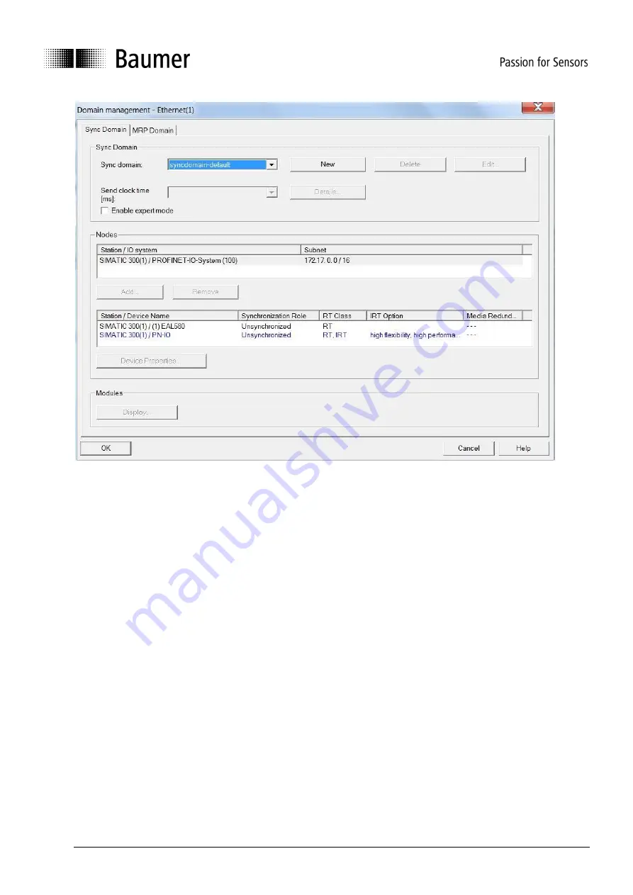
4.4.2. Real-Time (RT) Class 1
In this class a typical cycle time of 100 ms or less is possible. The bus system allows for standard Ethernet
components.
Topology planning is not mandatory, but where implemented (e. g. for retrieving feature
„Support device
replacement without exchangeable medium
”), make sure ports P1/P2 are correctly assigned as planned.
4.4.2.1.
Address assignment within the process image
Access to the
encoder’s input and output data takes place via addresses within the PLC’s process image.
Assign these addresses according to the needs of the PLC software.
Go to the Step7
®
HW Config. window and click on the encoder symbol on the bus rail to select it. Bottom left
in the module window the various encoder modules are shown. A double click on submodule 1.2 (e. g.
"telegram 860") opens
the property window with tab „addresses“.
Enter the start address of the respective address range or accept the
system’s proposal. Identical or
overlapping addresses for input and output are possible.
The process image (PI) will be that of the cyclic main program OB1 (not synchronized).


