


BE1-47N Testing
5-1
SECTION 5 • TESTING
GENERAL
The following procedures verify operation and calibration of the relay.
Results obtained from these procedures may not fall within specified tolerances. When evaluating results,
consideration must be given to three prominent factors.
&
The inherent error of the test equipment used.
&
The inconsistent method of testing (i.e. Timing start signal).
&
The tolerance level of external components used in the test setup.
OPERATIONAL TEST PROCEDURES
Negative Sequence Voltage Pickup and Dropout
To fully test the designed-in accuracy of the BE1-47N relay requires a simultaneous test of the three phases.
Such a comprehensive test involves careful monitoring of all phase voltages and phase angles, and the
calculation of the negative sequence voltages values. However, it is possible to obtain confirmation of the
essential integrity of the relay without resorting to methods that are more suited to a laboratory.
Accordingly, the following single-phase verification test is offered as an adequate test that is easy to setup
and execute. This will confirm relay accuracy and calibration.
STEP 1. Adjust the NEGATIVE SEQUENCE PICKUP setting to the "K" position (20%).
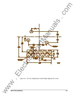
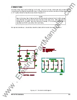
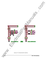
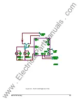
STEP 2. Short or jumper input terminal #7 (phase B) to #8 (phase C) (Figure 5-1).
STEP 3. Apply an input voltage at nominal frequency from terminal #6 (phase A) to #7 (phases B and C)
based on the sensing input ranges listed below.
Sensing Input Range
Voltage Input
3 - 120V/60 Hertz
4 - 100V/50 Hertz
5 - 208V/60 Hertz
6 - 173V/50 Hertz
41.57 Vac +2.08 Vac, 60 Hertz
34.64 Vac +1.73 Vac, 50 Hertz
72.05 Vac +3.60 Vac, 60 Hertz
59.93 Vac +3.00 Vac, 50 Hertz
RESULT: Negative Sequence Voltage Pickup LED should turn ON at this point.
STEP 4. Vary the input to verify the setting.
STEP 5. Lower the input voltage until the pickup LED turns OFF and record the input voltage.
RESULT: Dropout should be within 2% of the pickup value (i.e. input voltage at time of pickup, LED ON).
Further pickup settings may be verified at this time. The following formulas determine the input voltages,
based on sensing range, that will cause the pickup LED to turn ON.
www
. ElectricalPartManuals
. com


