background image

BE1-47N General Information

1-1

SECTION 1 • GENERAL INFORMATION

PURPOSE

BE1-47N Voltage Phase Sequence Relays respond to negative sequence voltage (V

2

) which results from

a fault or misconnection on a balanced, three-phase system.

APPLICATION

BE1-47N relays are designed to protect equipment from damage caused by phase failure, reverse phase
sequence, phase unbalance, undervoltage, or overvoltage.

The relay detects reverse phase connection of lines, transformers, motors, generators, and synchronous
condensors and is often applied in automatic transfer schemes to assure connection of proper phase rotation
as well as voltage conditions. When used in motor protection, the relay will provide protection by preventing
start-up of the motor for open phase or reverse phase condition and by tripping the motor off line for phase
unbalance, undervoltage or overvoltage conditions.

Negative sequence voltage is the result of any unequal phase condition on the source. This can be due to
unequal single phase loads on the system or unequal transformer impedances between the phases. A 1%-
2% level can normally be expected in an industrial supply. Any significant increase above this level can be
an indication of a power service problem and could lead to serious plant problems. The BE1-47N has the
ability to detect negative sequence voltage levels of this magnitude.

Undervoltage and voltage balance relays have traditionally been applied for the protection of induction
motors from operating with one phase open. These relays may not reliably detect this condition due to the
back emf of the motor on the open phase. However, an induction motor, with a starting current of 6 per unit,
will generate a negative sequence voltage of 16% if fully loaded when a fuse blows. The negative sequence
voltage will be somewhat reduced if the motor is not fully loaded. The sensitivity of the BE1-47N and its
insensitivity to frequency allow reliable protection to be applied to motors.

Motor losses and current unbalance increase with the negative sequence voltage level. The increased loss
due to negative sequence voltage is not a function of motor load but is independent. A machine operating
with 3.5% negative sequence voltage will have its losses increased by 25%. A blown fuse on a power factor
correction capacitor bank can result in significant negative sequence voltage increase. The effect of this
condition can be costly.

BE1-47N relays can be applied to protect motor buses from an open phase. It can also be applied to protect
critical individual motors, static, and nonrotating loads from the effects of negative sequence voltage.

A choice of time delay characteristics allows the relay to respond in the desired manner for a wide variety
of transient and fault conditions.

BE1-47N relays may also be used to provide over/undervoltage protection as well. A separate time delay
is utilized to prevent shutdown of equipment for minor voltage dips and to permit sequential operation when
the relay is being used in a supervisory capacity.

PHASE ROTATION SENSITIVITY

Relays that operate using phase-to-phase voltage to determine negative sequence are sensitive to phase
rotation.  BE1-47N Voltage Phase Sequence relays are phase rotation sensitive.  Unless otherwise noted,
all connections shown in this manual assume ABC rotation. 

www 

. ElectricalPartManuals 

. com

Summary of Contents for BE1-47N

Page 1: ...INSTRUCTION MANUAL FOR VOLTAGE PHASE SEQUENCE RELAY BE1 47N Publication 9170400990 Revision F 02 01 w w w E l e c t r i c a l P a r t M a n u a l s c o m...

Page 2: ...this manual INTRODUCTION This Instruction Manual provides information concerning the operation and installation of BE1 47N Voltage Phase Sequence Relay To accomplish this the following is provided Spe...

Page 3: ...ebruary 2001 It is not the intention of this manual to cover all details and variations in equipment nor does this manual provide data for every possible contingency regarding installation or operatio...

Page 4: ...3 2 Outputs 3 2 Indicators 3 2 Targets 3 2 Power Supply 3 3 Power Supply Status Output 3 3 SECTION 4 INSTALLATION 4 1 General 4 1 Relay Operating Precautions 4 1 Dielectric Test 4 1 Mounting 4 1 Conn...

Page 5: ...motor on the open phase However an induction motor with a starting current of 6 per unit will generate a negative sequence voltage of 16 if fully loaded when a fuse blows The negative sequence voltage...

Page 6: ...d the packing list to ensure that they agree SAMPLE STYLE NUMBER Style number identification chart Figure 1 1 defines the electrical characteristics and operational features included in BE1 47N relays...

Page 7: ...ac 5 0 W 12 0 VA Type R power supply initially requires 14 Vdc to begin operating Once operating the voltage may be reduced to 12 Vdc and operation will continue Target Indicators Magnetically latched...

Page 8: ...0 1 to 9 9 seconds in increments of 0 1 seconds with an accuracy of 5 of the time selected Inverse Time Adjustable over the range of 01 to 99 in increments of 1 Accuracy within 5 or 50 ms whichever is...

Page 9: ...mage or degradation of performance Isolation In accordance with IEC 255 5 and ANSI IEEE C37 90 one minute dielectric high potential tests as follows All circuits to ground 2121 Vdc Input to output cir...

Page 10: ...ixteen position thumbwheel switch that provides adjustment of the UNDERVOLTAGE PICKUP point from 2 to 32 below nominal in increments of 2 Settings correspond to percentage levels as indicated on the f...

Page 11: ...to percentage levels as indicated on the front panel M OVERVOLTAGE Indicator Red LED turns ON when system voltage exceeds the OVERVOLTAGE pickup setting N OVERVOLTAGE TIME DELAY Thumbwheel switch prov...

Page 12: ...3 1 Functional Block Diagram VOLTAGE SENSING Negative Sequence Voltage Three phase system voltage is supplied to 120 208V 100 173V nominal 50 60 hertz potential transformers PTs These PTs are an integ...

Page 13: ...rse Time Characteristic Curves Instantaneous Time is designated by a Time Delay setting of 00 Instantaneous response time is less than 50 milliseconds When evaluating inverse curves for the overvoltag...

Page 14: ...BE1 47N Functional Description 3 3 w w w E l e c t r i c a l P a r t M a n u a l s c o m...

Page 15: ...owing table Table 3 1 Wide Range Power Supply Voltage Ranges Power Supply Style Chart Identifier Nominal Voltage Voltage Range Low Range R 24 Vdc 12 to 32 Vdc Mid Range O P S 48 125 Vdc 120 Vac 24 to...

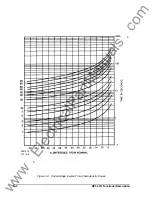
Page 16: ...500 MULTIPLES OF PICK UP SETTING T I M E I N S E C O N D S 1 0 2 0 3 0 4 0 5 0 6 0 7 0 8 0 9 0 L A I D E M I T 01 02 03 05 07 10 20 30 40 50 60 80 99 D2818 17 07 31 98 Figure 3 2 Negative Sequence Vol...

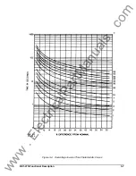
Page 17: ...3 6 BE1 47N Functional Description D2818 15 07 31 98 Figure 3 3 Undervoltage Inverse Time Characteristic Curves w w w E l e c t r i c a l P a r t M a n u a l s c o m...

Page 18: ...BE1 47N Functional Description 3 7 D2818 16 07 31 98 Figure 3 4 Overvoltage Inverse Time Characteristic Curves w w w E l e c t r i c a l P a r t M a n u a l s c o m...

Page 19: ...s relay is to be installed it is suggested that the connecting plugs of the relay be removed and the cradle withdrawn from the case so as not to produce false readings during the wiring insulation tes...

Page 20: ...BE1 47N Installation 2 02 01 D1427 01 Figure 4 1 S1 Case Panel Drilling Diagram Semi Flush Mounting Figure 4 2 S1 Case Outline Dimensions Front View w w w E l e c t r i c a l P a r t M a n u a l s c...

Page 21: ...ON OF WASHERS OVER THE BOSS TO TIGHTEN THE RELAY AGAINST THE PANEL CASE Figure 4 3 S1 Case Single Ended Semi Flush Mounting Outline Dimensions Side View Figure 4 4 S1 Case Single Ended Projection Moun...

Page 22: ...ON OF WASHERS OVER THE BOSS TO TIGHTEN THE RELAY AGAINST THE PANEL CASE Figure 4 5 S1 Case Double Ended Semi Flush Mounting Outline Dimensions Side View Figure 4 6 S1 Case Double Ended Projection Moun...

Page 23: ...BE1 47N Installation 4 5 Figure 4 7 S1 Case Single Ended Panel Drilling Diagram Rear View w w w E l e c t r i c a l P a r t M a n u a l s c o m...

Page 24: ...4 6 BE1 47N Installation Figure 4 8 S1 Case Double Ended Panel Drilling Diagram Rear View w w w E l e c t r i c a l P a r t M a n u a l s c o m...

Page 25: ...BE1 47N Installation 4 7 Figure 4 9 Semi Flush Mounting Outline Dimensions Rear View w w w E l e c t r i c a l P a r t M a n u a l s c o m...

Page 26: ...4 8 BE1 47N Installation Figure 4 10 S1 Case Projection Mounting Outline Dimensions Rear View w w w E l e c t r i c a l P a r t M a n u a l s c o m...

Page 27: ...te lead to the ground bus from each relay CONNECTIONS Incorrect wiring may result in damage to the relay Be sure to check model and style number before connecting and energizing the particular relay T...

Page 28: ...4 10 BE1 47N Installation Figure 4 12 Sensing Input Connections w w w E l e c t r i c a l P a r t M a n u a l s c o m...

Page 29: ...4 11 BE1 47N Installation Figure 4 13 Typical Internal Connection Diagram with Optional Output Contacts Normally Open w w w E l e c t r i c a l P a r t M a n u a l s c o m...

Page 30: ...le phase verification test is offered as an adequate test that is easy to setup and execute This will confirm relay accuracy and calibration STEP 1 Adjust the NEGATIVE SEQUENCE PICKUP setting to the K...

Page 31: ...PU V2L L VN VAB S 30 VN 3 Solving for VAB Magnitude VAB V2PU 3 VN where VN 120V for Sensing Input Range 3 208V for Sensing Input Range 5 20 V2 0 2 per unit V2 with Phase B shorted to Phase C For 120V...

Page 32: ...l as the overvoltage 59 and the undervoltage 27 functions of the relay operate similarly and can be tested using the same philosophy In order to reduce the amount of redundant procedural steps only th...

Page 33: ...e values are at 2 times actual pickup value STEP 5 Measure and record the interval from initiate to contact closure at case terminals 1 and 10 RESULT 47N Inverse Time should be 5 96 0 298 seconds Furt...

Page 34: ...BE1 47N Testing 5 5 Figure 5 2 Test Circuit Diagram 27 59 w w w E l e c t r i c a l P a r t M a n u a l s c o m...

Page 35: ...e entire relay cradle assembly preferably in its case IN HOUSE REPAIR Replacement parts can be purchased locally The quality of replacement parts must be at least equal to that of the original compone...

Page 36: ...erence to Service Manual 9 1704 00 620 Added Phase Rotation Sensitivity to Section 1 Updated the Dielectric Test information Changed Input Voltage Range and Burden Data in Power supply table in Specif...

Reviews: