BE1-47N Testing
5-3
Overvoltage Pickup and Dropout
STEP 1. Adjust the OVERVOLTAGE PICKUP setting to the "E" position (10%).
STEP 2. Apply 1.10 times the nominal input value (110%) across terminals #7 (phase B) and #8 (phase
C).
RESULT: Overvoltage pickup LED should turn ON.
STEP 3. Vary the input to confirm the value.
STEP 4. Lower the input until the pickup LED turns OFF and record the input value.
RESULT: Dropout should be within 2.0% of the pickup value (i.e. input voltage at time of pickup, LED ON).
Undervoltage Pickup and Dropout
STEP 1. Adjust the UNDERVOLTAGE PICKUP setting to the "E" position (10%).
STEP 2. Apply 0.90 times the nominal input value (90%) from terminal #7 (phase B) to #8 (phase C).
RESULT: Undervoltage pickup LED should turn ON.
STEP 3. Vary the input to confirm the value.
STEP 4. Raise the input until the pickup LED turns OFF and record the input value.
RESULT: Dropout should be within 2.0% of the pickup value (i.e. input voltage at time of pickup, LED ON).
VERIFICATION TESTS
Definite Time Verification
The definite time circuitry for the negative sequence voltage function (47N) as well as the overvoltage (59)
and the undervoltage (27) functions of the relay operate similarly and can be tested using the same
philosophy. In order to reduce the amount of redundant procedural steps, only the overvoltage function (59)
will be addressed.
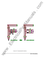
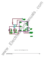
STEP 1. Connect the test setup as shown in Figure 5-2, Test Circuit Diagram.
STEP 2. Adjust the OVERVOLTAGE TIME DELAY to 33.
STEP 3. Adjust the OVERVOLTAGE PICKUP setting to the "A" position (2%).
STEP 4. Adjust the voltage source to 1.20 times the nominal input value (120%) from terminal #7 (phase
B) to #8 (phase C).
STEP 5. Close switch S1 to initiate timer. (Note: PICKUP LED turns ON.) Timer should time out at 3.3
s5%.
Inverse Time Verification
Due to the similarities in inverse timing for the functions of this relay, only the negative sequence function
is addressed. The remaining functions can be verified using the same test philosophy.
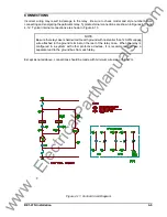
STEP 1. Connect the test setup as indicated in Figure 5-1.
STEP 2. Make the following relay front panel adjustments:
Negative Sequence Pickup - "B" (4%) position
Negative Sequence Time Delay - 10
STEP 3. Short or jumper case terminal #7 (phase B) to #8 (phase C).
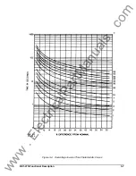
STEP 4. Apply the following input voltage from terminal #6 (phase A) to #7 (phase B and C) according to
www
. ElectricalPartManuals
. com

