BE1-47N Functional Description
3-1
V
C
T A R G E T
4 7 N
P O W E R S U P P L Y
S T A T U S
D 2 8 1 8 - 1 2
0 7 - 3 0 - 9 8
V
B
V
A
P H A S E
S H I F T
P I C K U P
S C A L I N G
L O W
P A S S
F I L T E R
R E F E R E N C E
L E V E L
N E G A T I V E
S E Q U E N C E
V O L T A G E
C O M P A R A T O R
A N D
4 7 N
A U X .
T I M I N G
T A R G E T
27/59
A U X .
O R
T I M I N G
T I M I N G
P O W E R
S U P P L Y
S E N S O R
5 9
2 7
U N D E R V O L T A G E
C O M P A R A T O R
U N D E R V O L T A G E
P I C K U P
O V E R V O L T A G E
P I C K U P
O V E R V O L T A G E
C O M P A R A T O R
L O W
P A S S
F I L T E R
P O W E R
S U P P L Y
S E N S O R
P O W E R
T O I N T E R N A L
C I R C U I T R Y
O P E R A T I N G
P O W E R
V
2
S E Q U E N C E
F I L T E R
SECTION 3 • FUNCTIONAL DESCRIPTION
General
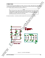
The following descriptions are referenced to the Functional Block Diagram, Figure 3-1 below .
Figure 3-1. Functional Block Diagram
VOLTAGE SENSING
Negative Sequence Voltage
Three-phase system voltage is supplied to 120/208V, 100/173V nominal, 50/60 hertz potential transformers
(PTs). These PTs are an integral part of the sequence filter and provide isolation, step-down scaling, and
phasor summation to eliminate the zero sequence component of the sensed voltages.
PHASE SHIFTING
The respective secondary voltages are phase s45
(
each, with respect to signal ground and then
summed to nullify the positive sequence component.
PICKUP SCALING
The resolved negative sequence voltage (V
2
) ac signal is then applied to the PICKUP scaling network
(switch S1 and its associated resistors). The PICKUP network establishes per unit (p.u.) values of V
2
for the
www
. ElectricalPartManuals
. com


