BE1-25 Testing
5-7
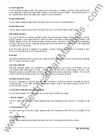
Output* only when bus and line input voltages are less than 30 volts.
Condition Switch
1
Up
2
Up
3
Up
4
Up
5
Down
Mode Switch
1
Up
2
Up
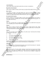
Output* only when bus and line input voltages are greater than 80 volts.
Condition Switch
1
Up
2
Down§
3
Up
4
Up
5
Up
Mode Switch
1
Up
2
Up
*
Contact is SYNC output for output option E or F; Voltage Monitor output for output option G or H.
§
The only valid use for the LB-LL Condition Switch No. 2 Down is when there is an independent output
relay for the Voltage Monitor output options G and H.
If the delta voltage option is present, it is factory set to 20 volts. (The timed SYNC output is inhibited if the
voltage difference between the line and the bus is greater than 20 volts.)
WARNING
!
Condition Switch No. 2, shown in Figure 2-2, must be OFF (Up) when output option E or F
is selected. Otherwise, SYNC outputs will occur under live line/live bus conditions without
benefit of the Sync-Check function.
NOT OV Testing
Step 6.
Test the NOT OV Mode of the Voltage Monitor as follows. (Proceed to step 7 if this mode is not
used.)
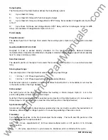
(a) Adjust the following front panel controls by applying the voltages stated below, adjusting each
control to the threshold where its LED indicator just turns ON. (Reference callouts L, N, F,
and G of Figure 2-1).
LB:
Adjust to 80 Vac.
DB/NOT OV:
Adjust to 120 Vac.
LL:
Adjust to 80 Vac.
DL/NOT OV:
Adjust to 120 Vac.
(b) Set TIME DELAY to 99 seconds. This allows the convenience of using in-phase voltages for
testing non-synchronous functions (without unwanted SYNC outputs).
(c) Apply simulated line and bus voltages adjusted to check the bus and line voltage criteria given
in Table 5-2. To be valid, an output must occur immediately after line and bus voltages are
applied.
www
. ElectricalPartManuals
. com


