


2-2
BE1-25 Human-Machine Interface
Callout
Control or Indicator
Function
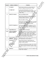
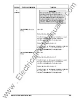
F
LL Indicator
Red LED lights when the line voltage exceeds the
reference voltage established by the LL setting.
LL Adjustment
Continuously adjustable from 10 to 135 Vac.
Adjustment is by small screwdriver through an access
hole in the front panel. CW rotation increases the
voltage setting.
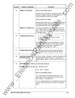
G
DL/NOT OV
Indicator
When in the NORMAL Mode:
Red LED lights when the line voltage is less than the
reference voltage established by the DL/NOT OV
setting that defines a dead line.
When in the NOT OV Mode:
Red LED lights when the line voltage does not exceed
the reference voltage established by the DL/NOT OV
setting that defines an overvoltage condition.
DL/NOT OV
Adjustment
Continuously adjustable over the range of 10 to 135
Vac. Adjustment is by small screwdriver through an
access hole in the front panel. CW rotation increases
voltage setting.
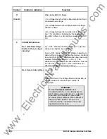
H
Target Reset Lever
Allows manual reset of the target.
I and J
PUSH-TO-ENERGIZE
OUTPUT Switches
Momentary pushbuttons are accessible by inserting a
1/8 inch diameter non-conducting rod through access
holes in the front panel. Switch I, when actuated,
closes the Sync Output contacts and (if specified) the
Auxiliary Sync Output contacts; Switch J closes the
(optional) Voltage Monitor Output contacts.
K
Target Indicator
(Optional)
Magnetically latching indicator which indicates that the
Sync Output relay is or was energized.
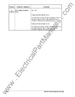
L
LB Indicator
Red LED lights when bus voltage exceeds the
reference voltage established by the LB setting that
defines a live bus condition.
LB Adjustment
Continuously adjustable over a range of 10 to 135 Vac.
Adjustment is by small screwdriver through an access
hole in the front panel. CW rotation increases voltage
setting.
M
V Indicator
Red LED lights whenever the (optional) Voltage Monitor
Output relay is energized.
www
. ElectricalPartManuals
. com


