BE1-25 Human-Machine Interface
2-1
SECTION 2
•
HUMAN-MACHINE INTERFACE
CONTROLS AND INDICATORS
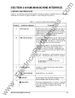
Table 2-1 lists and briefly describes the operator controls and indicators of the BE1-25 Sync-Check Relay.
Reference the callouts A through P to Figure 2-1 and Q through S to Figure 2-2.
Table 2-1. Location of Controls and Indicators
Callout
Control or Indicator
Function
A
SYNC Indicator
Red LED lights when an in-sync condition has been of
sufficient duration to match the TIME DELAY setting.
Lighting of the LED coincides with closure of the Sync
Output contacts. The LED extinguishes when 52b
opens or the in-sync condition ceases.
B
TIME DELAY Selector
Thumbwheel switches establish the time delay between
sensing the desired in-sync condition and closing the
Sync Output contact. Time delay is in units of seconds
or of cycles, according to the option selected.
Option A6: Adjustable in 1-second increments over a
range of 01 to 99 seconds when multiplier switch
(callout D) is in the X 1.0 position. Alternatively, the
range is 0.1 to 9.9 seconds with the multiplier switch in
the X 0.1 position.
Option A7: Adjustable in 1-cycle increments from 1 to
99 cycles. The multiplier switch (callout D) is omitted.
NOTE
A setting of 00 will inhibit closing of the
SYNC output.
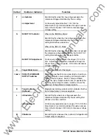
C
POWER Indicator
LED lights to indicate that the relay power supply is
functioning properly.
D
TIME DELAY Multiplier
Switch
Explained above; see callout B.
E
∆
V Indicator
Red LED lights when the difference between the bus
and line voltage is less than the
∆
V setting.
∆
V Adjustment
Continuously adjustable from 1 to 135 Vac. Adjustment
is by small screwdriver through an access hole in the
front panel. CW rotation increases the voltage
difference setting.
www
. ElectricalPartManuals
. com


