


3-2
BE1-25 Functional Description
0 1 - 3 0 - 0 1
D 1 0 5 8 - 0 4 . v s d
O P E R A T I N G
P O W E R
B U S
LINE
E X P A N D
P H A S E
A N G L E
OPTION
OPTIONAL
E X T E R N A L
C O N T A C T S
L B
D B O R B O V
LL
DL OR LOV
52b
P O W E R
S U P P L Y
C R O S S
Z E R O
Z E R O
C R O S S
P H A S E
D I F F E R E N C E
M E A S U R E M E N T
P O W E R
-2 OR -3
J U M P E R
O N P C B
TO INTERNAL
CIRCUITRY
A N D
A N D
O R
P O W E R
S U P P L Y
S E N S O R
P H A S E
A N G L E
S E L E C T O R
C O M P A R A T O R
A N D
A N D
TIMER
TIME DELAY
S W I T C H E S
P H A S E
SYNC.
O U T P U T
SYNC.
O U T P U T
AUX.
O U T P U T
P.S. STATUS
ISOLATION
MINIMUM
V O L T A G E
D E T E C T I O N
ISOLATION
FILTER
ISOLATION
FILTER
FRONT PANEL SETTINGS
P E A K O R A V G
D E T E C T O R
V
LL LB IF MODE 1:
(LL OV)(LB OV) IF MODE 2
L B
D B O R B O V
LL
DL OR LOV
V O L T A G E
M O N I T O R
SELECTION
LOGIC
M O D E
S W I T C H E S
CONDITION
S W I T C H E S
M O N I T O R
A C C E P T
P A T H S
A L T E R N A T E
M O N I T O R
V O L T A G E
O U T P U T
OPTION
D E P E N D I N G
VOLT.
SYNC-CHECK CIRCUITRY
VOLTAGE MONITOR OPTIONS
.
.
.
O N O U T P U T
P E A K O R A V G
D E T E C T O R
P E A K O R A V G
D E T E C T O R
P E A K O R A V G
D E T E C T O R
P E A K O R A V G
D E T E C T O R
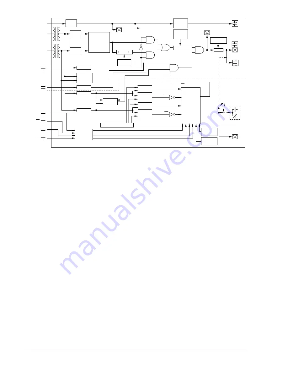
Figure 3-1. Functional Block Diagram
Minimum Voltage Detection
Minimum voltage detection circuitry enables the TIME DELAY timer when both line and bus are within
operating range of the relay. Voltage sensing circuits are guaranteed to operate at a minimum voltage of
60 volts. They are guaranteed not to operate at voltages less than 20 volts. Some units may operate at
voltages in between these two levels because of the individual characteristics of specific components.
Minimum voltage detection is usually in the range of 45 to 55 volts.
Contact Sensing Options
Before any relay output can occur, there must be an initiating signal from external contacts. Contact
sensing circuitry allows the relay to monitor circuit breaker status (52b) and various conditions selected by
the user. (Contact requirements are provided in the Specifications.)
In any sync-check relay, all of the contact sensing inputs supplied must use one of two methods.
1.
Isolated sensing (Option 1-5), uses current supplied by the relay to monitor the isolated contacts.
2.
Non-isolated sensing (Option 1-4), monitors an external dc source whose nominal voltage is equal
to the input to the BE1-25 power supply.
Power Supply
Basler Electric enhanced the power supply design for unit case relays. This new design created three,
wide range power supplies that replace the four previous power supplies. Style number identifiers for
these power supplies have not been changed so that customers may order the same style numbers that
they ordered previously. The first newly designed power supplies were installed in unit case relays with
EIA date codes 9638 (third week of September 1996). Relays with a serial number that consists of one
alpha character followed by eight numerical characters also have the new wide range power supplies. A
benefit of this new design increases the power supply operating ranges such that the 48/125 volt selector
is no longer necessary. Specific voltage ranges for the three new power supplies and a cross reference to
the style number identifiers are shown in Table 3-1.
www
. ElectricalPartManuals
. com


