BARTEC BENKE HYGROPHIL H 4230-12 Ex Zone II Operating Instructions Manual Download Page 89

Maintenance 

83 

Operating Instructions  HYGROPHIL® H 4230-12  BA 060207  

6.10


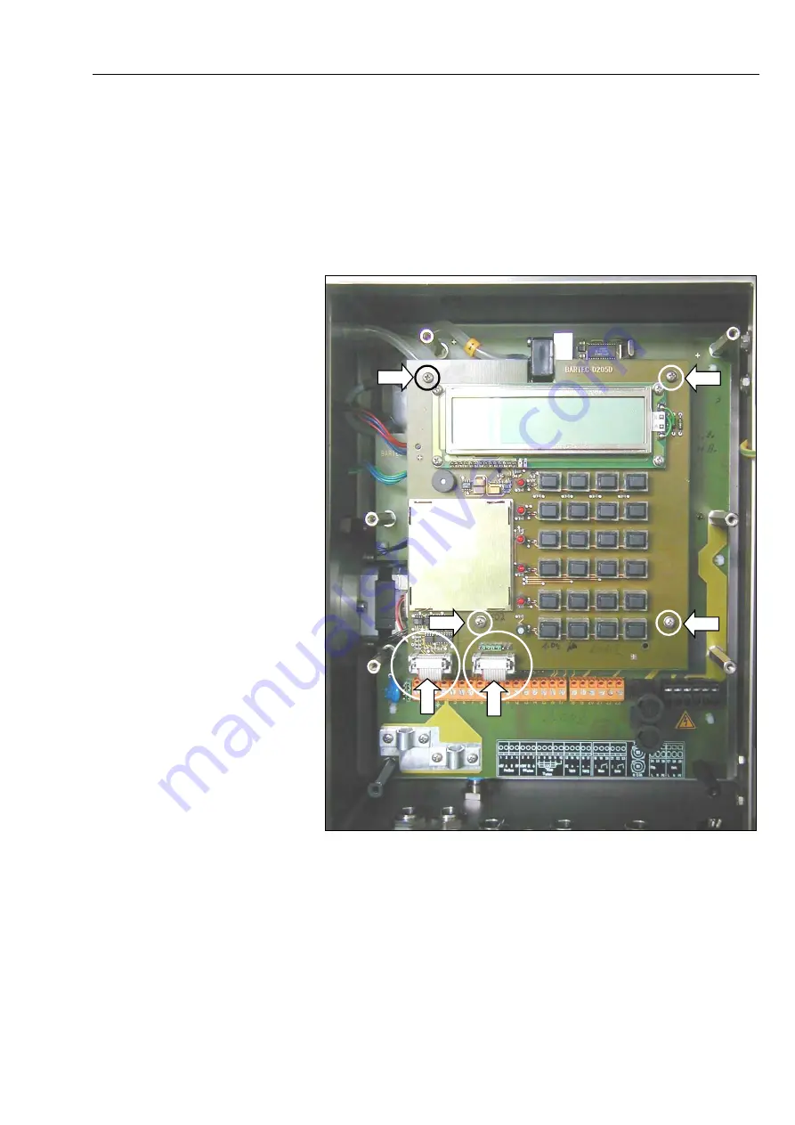
Replacing the Display-/ Profibus-
board 

  Disconnect the device from power supply before starting any work at the 

electronics. 

  Observe the safety precautions according to chapter 2. 

  Disconnect the two connectors and unscrew the four attachment screws. 


  Take the board carefully out and insert the replacement board. 

  Fix the board with the four screws and reconnect the two connectors. 


Summary of Contents for HYGROPHIL H 4230-12 Ex Zone II

Page 1: ...30 94239 Gotteszell Deutschland Telefon 49 0 9929 301 0 Telefax 49 0 9929 301 112 E Mail gotteszell bartec benke de Internet www bartec benke de HYGROPHIL H 4230 12 Ex Zone II Operating Instructions S...

Page 2: ......

Page 3: ..._______15 1 5 1 Basic equipment ___________________________________15 1 5 2 Accessories _______________________________________15 1 5 3 Spare parts _______________________________________19 16 01 08 1...

Page 4: ...______ 56 5 2 4 4 Hose heating controller ______________________________ 56 5 2 4 5 Compressed air control______________________________ 56 5 2 4 6 Flow setting_______________________________________...

Page 5: ..._________93 8 3 1 Service channel ____________________________________93 8 3 2 Measured value channel _____________________________94 8 3 3 Arithmetic value channel _____________________________95 8 3...

Page 6: ...art of this document may be reproduced processed or distributed in any form or by any means without the prior written permission of BARTEC BENKE Copyright 2018 by BARTEC BENKE Schulstra e 30 D 94239 G...

Page 7: ...y methods if at all HYGROPHIL H 4230 uses a microprocessor to calculate all humidity related variables in various scales and in addition to automatically monitor the unit itself As a result maintenanc...

Page 8: ...ordance with DIN 50012 and does not require any calibration It is one of the most reliable methods used to measure gas humidity Usually however this measurement procedure is subject to limits if the g...

Page 9: ...HYGROPHIL H 4230 12 BA 060207 Gas sampling hose Connecting cable for hose heating Water container Electronics enclosure Measuring chamber enclosure Earth connection Rinse valve SILAS Controller Compre...

Page 10: ...ics unit and further processed there The measuring cell is constantly fed with water from the storage tank by a hose pump The water level in the measuring cell is monitored by a sensor The pressure in...

Page 11: ...sure reduction controller If the over pressure of the measuring gas shall be used to convey it into the measuring chamber the heatable pressure reduction controller with filter must be installed at th...

Page 12: ...tings of the SILAS Controller are factory made see ta ble below They guarantee a safe operating in hazardous zone II The switch S1 must be turned into position 1 to monitor the rinse function The sett...

Page 13: ...Auxiliary temperatures T1external via ext temperature sensor Tinternal for compensating HT Dew point temperature DT Absolute humidity MH Specific humidity SH Volumetric water vapour content Vol Parti...

Page 14: ...cessible together with its display signal lamps and operating keys 1 3 10 1 Keys The measurement variables are displayed by simply pressing a key The keys that can be pressed to display the measuremen...

Page 15: ...partial water vapour pressure of the gas to be meas ured Display of the absolute humidity of the gas to be measured Display of the specific humidity of the gas to be measured Display of the enthalpy o...

Page 16: ...emperature Tint Standby the pump speed is decreased by a factor of 10 while the setpoint value for the differential pressure is fixed Key for changing the slave address and displaying the baud rate Te...

Page 17: ...sage is present red The PROFIBUS is exchanging data green 1 3 10 3 Display The display is made up of two rows and is backlit The measurement variables called using the keyboard are displayed togeth er...

Page 18: ...compensating the humid temperature For measuring temperature dependent humidity variables such as relative humidity RH or enthalpy h you have the option of installing an external temperature sensor T1...

Page 19: ...etric content H2OVol 2 100 0 1 Absolute humidity MH 15 1000 g kg 1 g kg Specific humidity SH 15 1000 g kg 1 g kg Enthalpy h 35 1000 kJ kg 1 kJ kg Current vapour pressure VP 10 1000 hPa 1 hPa Saturatio...

Page 20: ...e with DIN 40050 Dimensions 450 410 150 mm without mount Assembly drill holes 347x330 mm 4 7x13mm M6 Weight Approx 12 5 kg Connections Electrical connection Screw terminals 0 5 1 5 mm2 cable feed via...

Page 21: ...4220 30 and 1 litre of surfactant Order number 241887 1 5 2 Accessories Measurement gas tube Type 4230 114 Flexible water resistant heating tube for feeding measurement gas without condensate max inpu...

Page 22: ...ensor external Type 4230 103 For monitoring the fill level in the water storage tank Order number 216424 Adapter for gas sampling hose Type 4230 00 044 DKR 3 8 to NPT 1 4 Order number 214017 Adapter f...

Page 23: ...pe 4220 100 Including filter cartridge 150 m CrNi Steel 1 4404 Order number 208686 Gas sampling sensor Type SP 2000 GF 150 Order number 214334 Sampling pipe for Gas sampling sensor Type SP 2000 SS Ord...

Page 24: ...ting Instructions HYGROPHIL H 4230 12 BA 060207 Wall holder Type 4220 36 Order number U 3401422036 Stand holder Type 4220 35 Order number U 3401422035 Pressure reduction controller with filter Type 42...

Page 25: ...e parts Tube pump cartridge Type 4230 104 Order number 216422 Measuring chamber with ejector Type 4230 301 Without probes Order number 202383 Water sensor Type 4230 302 For monitoring the fill level i...

Page 26: ...tructions HYGROPHIL H 4230 12 BA 060207 Probe TT Type 4230 304 Order number 202411 Probe HT Type 4230 305 Order number 202410 Proportional valve Type 4230 308 Order number 202781 Display PROFIBUS boar...

Page 27: ...filter for standard filter Type 4220 106 150 m Cr Ni steel 1 4404 Order number U 116006 Replacement filter Type GF 150 for Gas sampling sensor SP 2000 0 1 m Order number 220232 Compressed air conditio...

Page 28: ...er connection nipple for measuring cell Type 4230 117 Measuring cell completely with ceramic ring without water connection nipple Type 4230 115 Order number 278353 Order number 278350 Special model fo...

Page 29: ...10 escape ejector chart no 4230 00 054 Order number 232458 Order number 222563 Nut M5 for measuring chamber or cap fastener 2x3 pc per meas chamber necessary Measuring cell bracket incl ejector Type 4...

Page 30: ...System description 24 Operating Instructions HYGROPHIL H 4230 12 BA 060207...

Page 31: ...our attention to dangers Open the enclosure door only if there is no explosive atmosphere is pre sent Switch the device off an wait at least 5 minutes for cooling down before opening the enclosure 2 2...

Page 32: ...be connected to the power supply in line with the specifications in these operating instructions see section 3 3 Make sure that you observe the relevant national regulations and the local provisions...

Page 33: ...he equipment or if safe operation of the equipment cannot be guaranteed for any other reason do not start up the equipment or if already in oper ation shut it down immediately Notify the local service...

Page 34: ...Safety precautions 28 Operating Instructions HYGROPHIL H 4230 12 BA 060207...

Page 35: ...ting up power installations rated for up to 1000 volts Select a solid vibration free vertical surface for installing the equipment In addition the installation location should be easily accessible for...

Page 36: ...diagram Fix four screws in the holes Attach the two fixation bars to the rear of the device Hook the device into the four screws Make sure that the equipment is aligned vertically This is important i...

Page 37: ...nt is not to be installed for stationary use you can fix it to the stand holder type 4220 35 see section 1 5 2 Accessories Place the unit on its front side Unscrew the two mounting struts from the rea...

Page 38: ...PE Do not disconnect the yellow green protective earth conductors or those labelled PE at any point Wire all power consumers within a complex system including the protec tive earth conductors in a sta...

Page 39: ...o terminals on the right and the two on the left must be short circuited to create one pole on the terminal strip Using a 2 conductor connection reduces the measurement accuracy be cause the supply co...

Page 40: ...the PROFIBUS cable through the two cable glands on the left Connect the PROFIBUS cable to terminals 2 PROFIBUS A and 3 PROFIBUS B If the unit is the last user in the PROFIBUS the two jumpers must be c...

Page 41: ...water is able to gather in a sagging arc to form a water sack that blocks the flow of air Even when the compressed air is switched on again later this alone will not be enough to remove such a water...

Page 42: ...elbows at the connections Avoid torsional movements during mounting Make sure that the axes of the hose run parallel and that the hose is not twisted Do not pull rolled hoses apart Unroll the hose If...

Page 43: ...gth Even small quantities of leakage air cause substantial measurement errors If the gas sampling hose has a length of more than 1 m its weight must be supported by one or more additional attachments...

Page 44: ...n at the bottom side of the device when operating with over pressure The compressed air connection should deliver maximum 17 5 Nl min at a pressure of 2 5 bar The pressure required depends on the nega...

Page 45: ...the compressed air connector stub on the measuring unit If the available supply pressure amounts to 5 bar or more the compressed air conditioner must always be used Although the maintenance unit is de...

Page 46: ...necessary to set the pressure Maximum efficiency of the ejector is obtained at a pressure of 5 bar The negative pressure in the customer system compared to the pressure in the measurement station mus...

Page 47: ...gin with and start measuring The proportional valve adjusts the air flow rate to the correct value in line with the pressure in the customer system and the flow relationships If the value of 2 bar set...

Page 48: ...for DP to 700 hPa and the tolerance for the proportional valve DP RANGE to 200 hPa Thermostat When delivered the thermostat is set to a temperature that prevents the pressure reduction controller from...

Page 49: ...ate of the device periodical The check intervals must be shorter than the programmed TIMEOUT of 2400 seconds 40 minutes lest the device will shut down and must be started anew Operating can be conside...

Page 50: ...ions due to a periodically rising water level as might be the case if the tension were not to be reduced Begin by pouring the surfactant into the storage tank Fill the storage tank with 2 litres of de...

Page 51: ...etector to terminals 5 6 and 7 Terminals 4230 5 6 7 Cable ext water detector red S brown black 3 8 2 Calibration Remove the water tank from the mount Hold the water detector s sensor up to the unfille...

Page 52: ...12 BA 060207 3 8 3 Installation Use two M 3 bolts and nuts to fix the external water detector to the inner side of the mounting strap front side of the tank attachment with the sensor side facing the...

Page 53: ...on for the system as a whole 4 2 Operating mode Once the operating voltage has been switched on the program version is displayed and the equipment begins by carrying out a self test The equip ment the...

Page 54: ...in operating mode The baud rate is then displayed briefly if the device is working connected to the bus Afterwards the current slave address is displayed briefly You are then asked whether you wish to...

Page 55: ...ected is highlighted If you press the ENTER key this option is confirmed without change and the next menu appears If you are requested to enter measurement variable designations when as signing the me...

Page 56: ...TER key you are taken to the next menu option Within the input masks you use the CLEAR key to correct entries see above When you enter values the system will only accept plausible entries mean ing tha...

Page 57: ...PAUSE TIME 30 EQUIP CONF 1 0 EQUIPM CONFIG T1 extern 1 0 EQUIPM CONFIG T internal 1 0 EQUIPM CONFIG TIMEOUT 1 0 EQUIPM CONFIG TIMEOUT s 1200 1 EQUIPM CONFIG WATERSEN_IN 1 0 0 EQUIPM CONFIG WATERSEN_E...

Page 58: ...You can assign any of the measurement variables to the analogue output ENTER Don t make any changes Select measurement variable press measurement variable key ENTER You can select the output current f...

Page 59: ...which the humidity of the gas to be measured lies start the measurements with the default value Observe the dew point temperature during the measurements If the measured dew point temperatures lie be...

Page 60: ...the target tem perature a fault message is output ENTER Don t make any changes Define target gas sampling hose temperature enter new value using key board ENTER 0 140 5 2 3 Programming the pump contr...

Page 61: ...used to compensate the humid temperature HT ENTER Don t make any changes 1 Switch on temperature sensor Tinternal 0 Switch off temperature sensor Tinternal The internal temperature sensor should alwa...

Page 62: ...ways lie below the ambient temperature even in winter and also if the input temperature is controlled externally it is possible to do without the hose heating In this case it is necessary to switch of...

Page 63: ...eyboard 100 999 ENTER After entering the nominal value enter the tolerance for the proportional valve Thus you define the limits for FLOW TOO LOW and FLOW TO HIGH The range for expedient values is 50...

Page 64: ...ke any changes Change reference pressure enter new value in hPa using keyboard ENTER 500 1500 5 2 4 8 Sensor calibration After installing or exchanging the temperature sensors you must enter their cal...

Page 65: ...g OFF the limit monitoring quit programming mode 1 Switching ON the limit monitoring ENTER Don t make any changes ENTER Confirm measurand or operand for defining the limit ENTER Don t make any changes...

Page 66: ...Programming 60 Operating Instructions HYGROPHIL H 4230 12 BA 060207...

Page 67: ...rt occur it is also necessary for the gas sampling hose to be inspected and cleaned on a regular basis Particular attention must be paid to making sure that the entire air supply system is completely...

Page 68: ...tially depends on the conditions of use In extreme cases the type and quantity of dirt in the air to be measured may make cleaning necessary every four weeks If the air flow rate displayed is too low...

Page 69: ...he surface of the water remains free of oil and grease thanks to the self cleaning effect Tar Tar is a fairly problematic form of contamination as the self cleaning effect does not work fully in this...

Page 70: ...ing chamber you need to remove all wires and hoses that run to the measuring chamber In order to avoid con fusing the wires and hoses during assembly it is a good idea to make a note of their position...

Page 71: ...Detach the compressed air hose this is done by pushing in the blue catch and simultaneously pulling out the hose In order to make it easier to press the catches you can use the hose de tachment aid i...

Page 72: ...Maintenance 66 Operating Instructions HYGROPHIL H 4230 12 BA 060207 Pull out the ejector outlet downwards while at the same time twisting it Detach the three upper M 5 A F 14 mounting nuts...

Page 73: ...Maintenance 67 Operating Instructions HYGROPHIL H 4230 12 BA 060207 Pull the measuring chamber carefully downwards and take it out of the enclosure...

Page 74: ...ting Instructions HYGROPHIL H 4230 12 BA 060207 6 3 4 Dismantling the measuring chamber Pull the two T pieces out of the measuring chamber enclosure together with the water detector Detach the three l...

Page 75: ...tions HYGROPHIL H 4230 12 BA 060207 Remove the two parts of the lower measuring chamber section pulling downwards Place the measuring chamber on the three lower threaded pins and press the middle meas...

Page 76: ...e the tulip to the measuring cell by using a screw driver or a simi lar tool 6 3 5 Changing the humid temperature sen sor Detach the knurled nut from the sensor mount and carefully extract the sensor...

Page 77: ...g to disassemble the measur ing chamber Detach the connector s knurled nut and remove the plug in connector Detach the knurled nut from the sensor mount and carefully extract the sensor Insert the new...

Page 78: ...rement Again use a pipe cleaner Middle measuring chamber section and measuring cell The interior of the measuring chamber often contains just greasy dirt The measuring cell may contain sludge In most...

Page 79: ...r is rising or if the mes sage FLOW TOO LOW appears although the supply of compressed air is sufficient and the station pressure is 200 hPa this means that the ejector is not working properly Clean th...

Page 80: ...e ejector is defective and must be replaced In this case please contact your service centre Outlet channels and inlet connection Extract the two outlet channels from the lower section of the measuring...

Page 81: ...Maintenance 75 Operating Instructions HYGROPHIL H 4230 12 BA 060207 Measuring cell type 4230 107 new Measuring cell type 4230 115 116 Component parts of the measuring chamber...

Page 82: ...g chamber make sure that the pin on the measuring cell snaps into place in the slot on the enclosure Check all silicone hoses prior to reassembly If they are no longer elastic and dimensionally stable...

Page 83: ...lf fill a plastic hose with water Hold the water detector s sensor up to the unfilled part of the hose The LED on the water detector must be off Then hold the water detector s sensor up to the filled...

Page 84: ...sing a peristalsis hose pump The pump can be changed quite easily when required Detach the two hose connections press the blue catch and extract the hose with the nipple Then squeeze the two catches o...

Page 85: ...the material can be used During cleaning the hose can briefly be subjected to temperatures of up to 200 C and pressures of up to 50 bar The gas sampling hose should only be cleaned mechanically if all...

Page 86: ...n the condensate separator 45 to the left or to the right Pull the condensate separator down to remove it Rinse the condensate separator carefully us ing this opportunity If there is a coating at the...

Page 87: ...aned or a new filter Insert the filter holder an fix it by turning it clockwise Attach the condensate separator The mark at the upper flange meets the mark at the valve hous ing Press the condensate s...

Page 88: ...the electronics enclosure door on the right Press in the fuse holder using a screwdriver and turn it a little anticlock wise Extract the fuse holder and exchange the fuse Insert the fuse holder toget...

Page 89: ...e device from power supply before starting any work at the electronics Observe the safety precautions according to chapter 2 Disconnect the two connectors and unscrew the four attachment screws Take t...

Page 90: ...tions of all connections or mark them distinctive Disconnect all cables and connectors Disconnect the three pressure hoses carefully Unscrew the seven attachment bolts Attention Do not unscrew the bla...

Page 91: ...ntenance 85 Operating Instructions HYGROPHIL H 4230 12 BA 060207 Connect the pressure hoses to their nipples according to the figure be low Reassemble the display profibus board according to section 6...

Page 92: ...connect the two blue hoses from the proportional valve For this press in hose catch at the nipple and pull out the hose at the same time Unscrew the two allen screws and take the valve out Insert the...

Page 93: ...SYSTEM O K The equipment is ready to work STANDBY Warning relay The equipment is in standby mode TIMEOUT Error relay A fault occurred for longer than the programmed TIMEOUT time Determine fault displa...

Page 94: ...y Although the proportional valve is fully closed too much air is being pumped through the measuring chamber close error see section 8 3 1 DaAdr 0A Bit 9 and Bit 17 Upon start up Pressure at the extra...

Page 95: ...measuring range limit Check conditions at the sam pling position Check programming menu PRG OUTPUT OVERRANGE A1 A2 Warning relay No fault at the device Warning when measurand is too high The value for...

Page 96: ...ve or below the value de fined in the SET LIMITS menu the warning relay is activated and the Fault LED lights up The current measurands are present at the analog output In the following cases will the...

Page 97: ...de This is where the command code is shown for queries and the status code is shown for responses from the measuring unit Input 0x01 Write 0x02 Read Output In the case of responses from HYGROPHIL addi...

Page 98: ...be requested Output The number of items of user data written or to be read is coded in this byte Byte 7 reserved Bytes 8 15 user data Input In the case of a write process the data to be written must...

Page 99: ...Bit 8 Open error proportional valve cannot open any further Bit 9 Close error proportional valve cannot close any further Bit 10 Error in external water detector Bit 11 Error in internal water detect...

Page 100: ...al temperature T1external 16 C 0 200 C Internal temperature Tinternal 20 C 0 100 C DaAdr 16 Preset SP Format Array 1 6 of Float Before you can write this variable you must first change to standby mode...

Page 101: ...0 g kg Specific humidity SH 16 g kg 1000 g kg Enthalpy H 20 kJ kg 1000000 kJ kg Saturation deficit DVP 24 hPa 5000 hPa Relative humidity due to T1external RHexternal 28 0 100 Volumetric water content...

Page 102: ...aAdr 31 OutputControlStatus Format Array 1 3 of Char 7 6 5 4 3 2 1 0 Value OK SignalHigh SignalLow Free Free Free Free Free Value OK 1 Value at analogue output within specified limits 0 Value at analo...

Page 103: ...0 mA 20 Current output 0 100 20 4 mA 30 Current output 0 100 0 20 mA 40 Current output 0 100 20 0 mA Default 10 SetpointNo Index for selecting the output variable 0 15 based on the table in DaAdr 10 a...

Page 104: ...T C 0 2 HT C 0 8 3 5 1 channel parameters DaAdr hex Identifier Memory Type Read out Format 40 Heating_w EERPOM read write dec Float 41 Heating_xp EERPOM read write dec Float 42 HeatingControlStatus RA...

Page 105: ...Error 1 Fault short circuit interruption on the hose heating 0 Hose heating OK D limit 1 D component limit exceeded 0 D component OK PID active 1 PID controller active i e xp range reached 0 P control...

Page 106: ...Record 54 PumpControlStatus RAM read write hex Char 55 PumpConfig EEPROM read write hex Char 57 EquipmentControlStatus RAM read write hex Char 58 EquipmentConfig EEPROM read write hex Char 53 Limit Ta...

Page 107: ...not activated DaAdr 54 PumpControlStatus Format Char 7 6 5 4 3 2 1 0 ON Pump on off FillMode Control NormalMode Control SM Error Free FillMode Status Nor malMode ON 1 The pump is switched on and runni...

Page 108: ...eased the status bits are left at 0 DaAdr 58 EquipmentChConfig Format Char Before you can write this variable you must first change to standby mode 7 6 5 4 3 2 1 0 Free Free External water de tector F...

Page 109: ...first change to standby mode Upper value of the limit monitoring HIGH LIMIT Default 100 DaAdr 5c DP Parameter Format Record Before you can write this variable you must first change to standby mode Pr...

Page 110: ...always be 0x00 Data address from channel description Byte 2 0x00 Byte 3 0x20 for dew point Offset from channel description Byte 4 0x00 Byte 5 0x00 Length of the data requested Byte 6 0x04 for 4 bytes...

Page 111: ...rom channel description standby mode 0x000B Byte 2 0x00 Byte 3 0x0B Offset from channel description Byte 4 0x00 Byte 5 0x00 Length of the data to be written Byte 6 0x01 for 1 byte Byte 7 Reserved 0x00...

Page 112: ...Operating Instructions HYGROPHIL H 4230 12 BA 060207...

Reviews: