


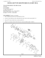


Operation and Maintenance Manual
495B ML TM (S)
47
Last Updated - 08/31/2016
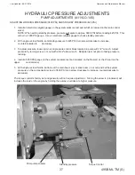
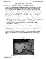
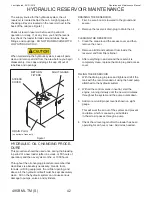
HYDRAULIC CYLINDER MAINTENANCE
Hydraulic cylinders provide force used to operate booms, attachment, and stabilizers. Proper maintenance of
cylinders will promote long life and smooth operation.
Inspect cylinders daily for leaks or damage and repair or replace as necessary. Lubricate cylinder grease fittings daily.
SEAL SERVICING
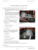
1. Remove cylinder from the machine.
2. Remove the bolts/screws from the gland.
NOTE: Some cylinders have screw-on gland caps, held in place with an allen head set screw. If so, remove
set screw and then removing gland cap using an adjustable chain wrench.
3. Remove hydraulic supply and return lines (including load lock valves if applicable) from cylinder to allow free
movement of rod.
4. Remove rod assembly from the cylinder barrel.
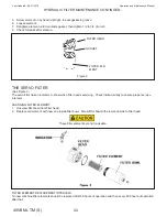
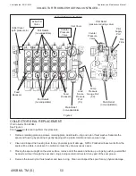
5. Unscrew the nut from the piston end of the rod and remove the piston and gland.
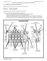
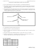
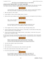
6. Before removing old seals, note position they are in for proper reassembly (see diagram on next page).
7. Clean and inspect all parts. If worn or damaged, replace them.
8. Install new seals, ensure order is as shown in diagram.
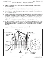
NOTE: Special pliers (part number 412-00409) can be used to aid in assembly (see photo on next page).
Install item # 10 before item # 8.
Heating item # 10, 7, and the stiff portion of # 1 in a 200° oven for 5 minutes will make it more pliable.
Some kits may contain extra seals.
When installing the wear rings, items # 2 & 6, put the cuts on opposite sides.
9. Start gland on rod and hammer on until it is past the stub.
10. Slide piston onto stub, ensure O-ring # 3 is on stub and piston is in proper orientation (small recess is O-ring side,
large recess is nut side).
11. Tighten nut to torque listed in parts manual.
12. Oil new cylinder seals lightly before installing rod assembly in cylinder barrel, oil barrel if necessary.
13. Reinstall gland cap, tighten bolts in a cross pattern to torque specified in parts manual.
14. Reinstall on machine and reattach hydraulics lines.
NOTE: The more common cylinders use the following tool sizes:
Hex head cap screws require 15/16" wrench.
Nut requires 3-1/8" wrench.
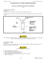
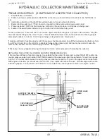
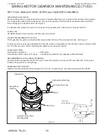
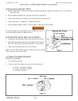
Cylinder shown may not be type used on your machine but is shown as a reference.
PISTON
STROKE
LIMITER
GLAND
HEX HEAD CAP
SCREWS
ROD
BUSHING
GREASE
FITTING
NUT
BARREL
BUSHING
GREASE
FITTING
(BUTT & TUBE ASSY)
Summary of Contents for 495B SD
Page 3: ...Introduction...
Page 7: ......
Page 16: ...Maintenance...
Page 19: ...Operation and Maintenance Manual 495B ML TM S 19 Last Updated 08 31 2016 SERVICE SCHEDULE...
Page 29: ...Hydraulic...
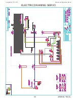
Page 57: ...Electrical...
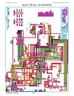
Page 58: ...Operation and Maintenance Manual Last Updated 08 31 2016 495B ML TM S 58 ELECTRICAL SCHEMATIC...
Page 78: ...Maintenance...
Page 88: ...Operation and Maintenance Manual Last Updated 08 31 2016 495B ML TM S 88 Structural...
Page 95: ...Trouble Shooting...


