Manual 2100-587J
Page
45 of 59
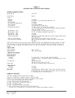
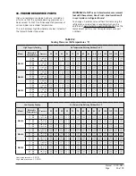
34. PRESSURE SERVICE PORTS
High and low pressure service ports are installed on
all units so that the system operating pressures can
be observed. Table 12 outlines expected pressures at
various indoor and outdoor temperatures.
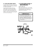
This unit employs high-flow Coremax valves instead of
the typical Shrader type valves.
Low side pressure ± 4 PSIG
High side pressure ± 10 PSIG
TABLE 12
Cooling Pressures (All Temperatures °F)
WARNING! Do NOT use a Schrader valve core removal
tool with these valves. Use of such a tool could result
in eye injuries or refrigerant burns!
To change a Coremax valve without first removing the
refrigerant, a special tool is required which can be
obtained at www.fastestinc.com/en/SCCA07H. See the
replacement parts manual for replacement core part
numbers.
High Capacity Cooling
Air Temperature Entering Outdoor Coil
°
F
Model
Return Air
Temperature
Pressure
50
55
60
65
70
75
80
85
90
95
100
105
110
115
WG3S2
75° DB
62° DB
Low Side
High Side
112
195
115
214
119
233
122
253
126
272
129
291
131
314
132
337
134
360
135
383
136
409
138
435
139
461
140
487
80° DB
67° DB
Low Side
High Side
124
201
127
220
131
239
134
259
138
278
139
297
140
319
140
341
141
363
141
389
148
413
149
440
151
468
152
495
85° DB
72° DB
Low Side
High Side
135
205
138
224
142
243
145
263
149
282
152
301
154
326
156
350
157
375
159
399
161
425
162
451
164
476
165
502
WG4S2
75° DB
62° DB
Low Side
High Side
117
197
119
216
121
235
123
255
125
274
127
293
128
316
130
339
131
361
132
383
133
410
135
438
136
466
137
494
80° DB
67° DB
Low Side
High Side
127
201
129
220
131
239
134
259
136
278
138
298
138
318
139
341
139
364
145
381
145
415
146
443
146
471
149
500
85° DB
72° DB
Low Side
High Side
141
203
143
223
145
243
148
263
150
283
152
303
152
326
153
349
153
372
154
396
156
422
158
449
160
478
162
508
WG5S2
75° DB
62° DB
Low Side
High Side
118
199
119
217
120
236
122
260
123
285
125
309
126
333
128
357
129
381
130
405
132
432
133
460
135
487
136
514
80° DB
67° DB
Low Side
High Side
129
205
130
224
131
247
131
270
132
292
132
315
134
339
137
363
139
387
143
394
143
438
145
465
146
492
148
519
85° DB
72° DB
Low Side
High Side
137
216
139
237
140
258
141
279
142
300
143
321
146
346
148
370
151
395
153
419
155
447
157
474
158
502
160
529
Low Capacity Cooling
Air Temperature Entering Outdoor Coil °F
Model
Return Air
Temperature
Pressure
50
55
60
65
70
75
80
85
90
95
100
105
110
115
WG3S2
75° DB
62° DB
Low Side
High Side
126
181
127
198
129
215
130
233
132
250
133
267
135
289
136
310
138
332
139
353
141
378
144
404
146
429
148
454
80° DB
67° DB
Low Side
High Side
134
184
134
201
135
218
135
236
136
253
136
270
137
291
137
312
138
333
138
358
140
380
142
406
144
432
146
458
85° DB
72° DB
Low Side
High Side
153
190
154
207
155
224
156
241
157
258
158
275
160
297
162
318
163
340
165
361
167
387
168
413
170
438
171
464
WG4S2
75° DB
62° DB
Low Side
High Side
122
184
124
201
125
218
127
236
129
254
131
272
131
291
132
312
133
335
134
359
135
381
137
407
139
435
141
463
80° DB
67° DB
Low Side
High Side
132
185
134
203
136
221
138
239
140
257
142
275
145
298
146
317
147
339
149
354
149
384
150
410
151
438
152
467
85° DB
72° DB
Low Side
High Side
145
187
147
205
149
223
152
241
154
259
156
278
156
397
157
319
158
343
159
369
161
390
163
415
164
443
165
472
WG5S2
75° DB
62° DB
Low Side
High Side
123
187
125
207
127
226
129
245
131
263
133
282
134
305
135
328
136
350
137
373
139
399
141
425
143
451
145
477
80° DB
67° DB
Low Side
High Side
134
192
136
211
138
230
139
248
141
267
143
286
144
308
145
331
146
353
148
367
153
402
155
429
156
456
158
483
85° DB
72° DB
Low Side
High Side
146
200
148
217
149
235
151
252
152
270
154
287
156
311
159
335
161
358
163
382
165
408
166
434
168
460
169
486
Summary of Contents for WG Series
Page 11: ...Manual 2100 587J Page 11 of 59 FIGURE 2A Mounting Instructions for WG3S2...
Page 12: ...Manual 2100 587J Page 12 of 59 FIGURE 2B Mounting Instructions for WG4S2 and WG5S2...
Page 15: ...Manual 2100 587J Page 15 of 59 FIGURE 6 Common Wall Mounting Installations...
Page 25: ...Manual 2100 587J Page 25 of 59 FIGURE 11 Gas Pipe Connection...

