Manual 2100-587J
Page
9 of 59
1. IMPORTANT
The equipment covered in this manual is to be
installed by trained, experienced service and
installation technicians. All duct work or portions
thereof not in the conditioned space should be properly
insulated in order to both conserve energy and prevent
condensation or moisture damage.
2. APPLICATION
This is a fan-assisted forced air gas furnace with electric
air conditioning for outdoor installation. A fan-assisted
furnace is equipped with an integral mechanical means
to draw products of combustion through the combustion
chamber and heat exchanger. The furnace installation
must conform with local building codes and ordinances
or, in their absence, with the National Fuel Gas Code
ANSI Z223.1 or CAN/CGA-B149.1, latest edition,
and the National Electrical Code ANSI/NFPA-7 or CSA
C22.1, latest edition. It is the personal responsibility
and obligation of the purchaser to contact a qualified
installer to assure that installation is adequate and is in
conformance with governing codes and ordinances.
3. DUCT WORK
The unit is designed for use with or without duct work
(see Warning on this page). Flanges are provided
for attaching the supply and return ducts. These
instructions explain the recommended method to
install the air cooled self-contained electric air
conditioning and gas heating unit and the electrical
wiring connections and gas piping to the unit. The
refrigerant system is completely assembled and
charged. All internal wiring is complete.
These instructions and any instructions packaged with
any separate equipment required to make up the entire
heating/cooling system should be carefully read before
beginning the installation. Note particularly “Starting
Procedure” and any tags and/or labels attached to the
equipment.
All duct work, supply and return, must be properly
sized for the design airflow requirement of the
equipment. Air Conditioning Contractors of America
(ACCA) is an excellent guide to proper sizing.
Refer to Table 9 in this Manual for maximum static
pressure available for duct design.
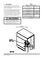
See Figure 3 and clearance information in Section 9
and Table 2 for additional information.
Design the duct work according to methods given by
the Air Conditioning Contractors of America (ACCA).
When duct runs through unheated spaces, it should
be insulated with a minimum of 1" of insulation. Use
insulation with a vapor barrier on the outside of the
insulation. Flexible joints should be used to connect
the duct work to the equipment in order to keep the
noise transmission to a minimum.
A 1
”
clearance to combustible material for the
first 3’ of duct attached to the outlet air frame
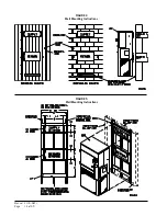
is required. See Wall Mounting Instructions and
Figures 2, 2A, 3 and 3A for further details.
Ducts through the walls must be insulated and all
joints taped or sealed to prevent air or moisture
entering the wall cavity.
Some installations may not require any return air
duct. A metallic return air grille is required with
installations not requiring a return air duct. The
spacing between louvers on the grille shall not be
larger than 5/8”.
Any grille that meets with the 5/8” louver criteria
may be used. It is recommended that Bard Return
Air Grille or Return Filter Grille be installed when
no return duct is used. Contact distributor or
factory for ordering information. If using a return
air filter grille, filters must be of sufficient size to
allow a maximum velocity of 400 fpm.
NOTE: If no return air duct is used, applicable
installation codes may limit this cabinet to
installation only in a single story structure.
4. HIGH ALTITUDE APPLICATIONS
Ratings of gas utilization equipment are based on
sea level operation and need not be changed for
operation at elevations up to 6,000
’
. For operation at
elevations above 6,000
’
and in the absence of specific
recommendations from the local authority having
jurisdiction, equipment ratings shall be reduced as
specified in Section 21.
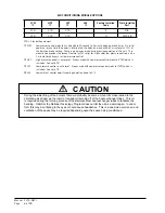
WARNING
In all cases, there must be a metal duct
connection made to the supply air flange,
and a 1" clearance to combustibles must be
maintained to this duct connection.
For free blow applications, a metal sleeve
must be used in the wall opening itself, again
maintaining a 1" clearance to combustibles.
Failure to use the sheet metal can cause fire
resulting in property damage, injury, or death.
INSTALLATION
Summary of Contents for WG Series
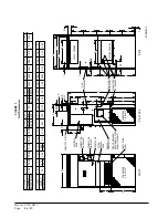
Page 11: ...Manual 2100 587J Page 11 of 59 FIGURE 2A Mounting Instructions for WG3S2...
Page 12: ...Manual 2100 587J Page 12 of 59 FIGURE 2B Mounting Instructions for WG4S2 and WG5S2...
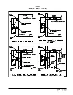
Page 15: ...Manual 2100 587J Page 15 of 59 FIGURE 6 Common Wall Mounting Installations...
Page 25: ...Manual 2100 587J Page 25 of 59 FIGURE 11 Gas Pipe Connection...


