Manual 2100-587J
Page
32 of 59
24. FILTERS
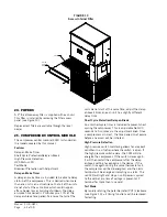
A 2" thick throwaway filter is supplied with each unit.
This filter is installed by removing the filter access
panel (see Figure 13).
Replacement filters are available through the local
dealer.
25. COMPRESSOR CONTROL MODULE
The compressor control module (CCM) is standard on
the models covered by this manual.
Features
Delay-on-Make Timer
Short Cycle Protection/Delay-on-Break
High Pressure Detection
HPC Status LED
Test Mode
Brownout Protection with Adjustment
Delay-on-Make Timer
A delay-on-make timer is included to be able to delay
startup of the compressor. This is desired when more
than one unit is on a structure so that all of the units
do not start at the same time which could happen
after a power loss or building shutdown. The delay-
on-make time period is 2 minutes plus 10% of the
delay-on-break time period. To ensure that all of the
FIGURE 13
Access Internal Filter
units do not start at the same time, adjust the delay-
on-break timer on each unit to a slightly different
delay time.
Short Cycle Protection/Delay-on-Break
An anti-short cycle timer is included to prevent short
cycling the compressor. This is adjustable from 30
seconds to 5 minutes via the adjustment knob. Once
a compressor call is lost, the time period must expire
before a new call will be initiated.
High Pressure Detection
High pressure switch monitoring allows for a lockout
condition in a situation where the switch is open. If
the high pressure switch opens, the CCM will de-
energize the compressor. If the switch closes again,
it will then restart the compressor after the delay-
on-break setting has expired on the device. If the
switch trips again during the same thermostat call,
the compressor will be de-energized and the alarm
terminal will be energized indicating an alarm. The
red LED will light and stay on until power is cycled
to the control or a loss of voltage is present at Y
terminal for more than ½ second.
Test Mode
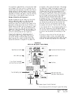
By rapidly rotating the potentiometer (POT) clockwise
(see Figure 14), all timing functions will be removed
for testing.
MIS-3237
FILTER
FILTER
SERVICE
DOOR
Summary of Contents for WG Series
Page 11: ...Manual 2100 587J Page 11 of 59 FIGURE 2A Mounting Instructions for WG3S2...
Page 12: ...Manual 2100 587J Page 12 of 59 FIGURE 2B Mounting Instructions for WG4S2 and WG5S2...
Page 15: ...Manual 2100 587J Page 15 of 59 FIGURE 6 Common Wall Mounting Installations...
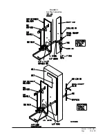
Page 25: ...Manual 2100 587J Page 25 of 59 FIGURE 11 Gas Pipe Connection...


