Manual 2100-671
Page
31 of 44
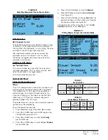
3. Press UP or DOWN keys to scroll to
System Config
;
press ENTER key.
4. Press UP or DOWN keys to scroll to
Return Air
Alarm A5
.
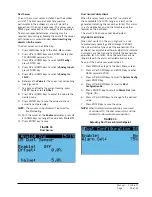
5. Press ENTER key to scroll to
Enable, Lower
Limit
or
Upper Limit
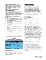
(see Figure 46).
6. Press UP or DOWN keys to disable the alarm or
change the limit values.
Emergency Ventilation Mode
If the emergency ventilation input at the LC is active,
the system will go into emergency ventilation mode. In
emergency ventilation mode, the economizers on the wall
units will be commanded to 100%. This mode is only
available when connected to the LC.
NOTE:
All units will receive the emergency ventilation
command. Wall units not equipped with
economizers will still engage the blower.
Electric Heat Option
Electric Heat Components
Electric Heating Element
The unit can be optionally equipped with 9kw or 18kw
of heat. The 9kw is a single stage heating element. The
18kw option comes equipped with two 9kw heating
elements that operate in two stage. The heating
elements are located downstream of the evaporator
coils and can be accessed through the upper control
panel door.
Thermal Overload
The heater assembly has a thermal overload wired in
series with the heating element. This device has a
cycling limit which opens at 130°F and resets at 80°F.
The limit is also equipped with a redundant thermal
fuse that will open at 150°F.
Electric Heat Operation
The heat strip will be activated on a call for heat. This
call can be generated by the LC or the wall-mount unit
operating in orphan mode.
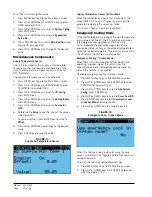
FIGURE 46
Adjusting Return Air Alarm Settings
Unit Disable Option
The unit is equipped with an input that can be used to
turn off the unit.
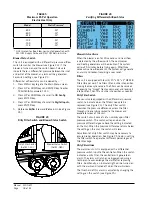
The unit disable input can be verified and adjusted by:
1. Press MENU key to go to the Main Menu screen.
2. Press UP or DOWN keys and ENTER key to enter
TECHNICIAN password 1313.
3. Press UP or DOWN keys to scroll to
I/O Config
;
press ENTER key.
4. Press UP or DOWN keys to scroll to
Digital Inputs
;
press ENTER key.
5. Press UP or DOWN keys to scroll to
Digital Ins 1/2
.
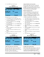
6. Reference
Disable
row and
En
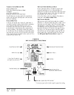
column (see Figure
47).
7. Press ENTER key to scroll to
Disable En
value.
8. Press UP or DOWN key to change value.
9. Press ENTER key to scroll to
Dir
.
10. Press UP or DOWN key to change direction (
N/O
or
N/C
), if applicable.
11. Press ESCAPE key several times to return to Main
Menu screen.
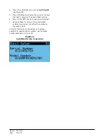
FIGURE 47
Unit Disable Option
Serial/Model Number Configuration
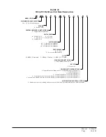
MEGA-TEC wall-mount units configure some settings
based on the model number that is input into the unit.
The model and serial number are entered at the factory,
and should be retained during a software update.
However, after a software update, it is best practice to
verify that the model and serial number is still present
and accurate. If the model and/or serial number is
missing or incorrect they will need to be re-entered.
To update serial/model numbers:
1. Press MENU key to go to the Main Menu screen.
2. Press UP or DOWN keys and ENTER key to enter
ENGINEER password 9254.
3. Press UP or DOWN keys to scroll to
Adv. Sys.
Config
; press ENTER key.

