


Manual 2100-671
Page
23 of 44
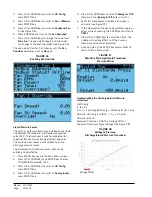
Test Mode
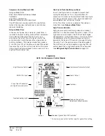
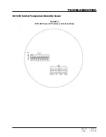
By rapidly rotating the potentiometer (POT) clockwise
(see Figure 30), all timing functions will be removed
for testing.
The conditions needed for the unit to enter test mode
are as follows: POT must start at a time less than or
equal to the 40 second mark. The POT must then be
rapidly rotated to a position greater than or equal to
the 280 second mark in less than ¼ second. Normal
operation will resume after power is reset or after the
unit has been in test mode for at least 5 minutes.
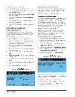
Brownout Protection with Adjustment
Brownout protection may be necessary if the utility
power or generator power has inadequate power to
prevent the voltage from dropping when the compressor
starts. This is rare but can happen if the generator
is undersized at the site or if the site is in a remote
location far from the main power grid. Under normal
circumstances, allowing the brownout to be ignored for
a time period should not be needed. The 8201-164 is
shipped with all the DIP switches in the 'off' or 'do not
ignore' position (see Figure 30).
If ignoring the brownout is needed because of the
above conditions, three preset timers can be set by DIP
switches in order to delay signaling a power brownout
for a specific length of time after compressor contactor
is energized. This allows the compressor a time period
to start even if the voltage has dropped and allows the
voltage to recover. This delay only happens when the
CC terminal energizes. The delay can be set to 500
milliseconds (A DIP switch), 1000 milliseconds (B DIP
switch) or 1500 milliseconds (C DIP switch); time is
not cumulative—only the longest setting will apply. If
the voltage recovers during the brownout time period,
the compressor will start.
If a brownout condition is detected by the 8201-164,
the troubleshooting light will flash blue. The light will
continue to flash until the cooling call is satisfied or
power is removed from the Y terminal. This condition
does not prevent operation, it only indicates that a
brownout condition was present at some point during
the cooling call. If a brownout condition is detected,
CC will be de-energized and will retry after the delay-
on-make timer is satisfied; this process will continue
until call is satisfied.
If user chooses the 'do not ignore' position when the
site has inadequate utility or generator power, this
could lead to the compressor never starting. The
control will see the brownout immediately and not start.
A common scenario and one that has been seen in the
field is when a unit or units switches from utility power
to generator power. With slower transfer switches, the
time delay between the utility power and generator
power didn’t cause a problem. The units lost power,
shut off and came back on line normally. With the
introduction of almost instantaneous transfer switches,
the millisecond long power glitch can be enough that
the compressor will start to run backwards. In this
scenario, the CCM will catch this and restart the units
normally.
High Pressure Safety Switch
All units have a high pressure switch as a safety device.
This device will open when pressure in the system
reaches 650 PSIG. The sensor is directly connected
to the dedicated compressor control module (see
High
Pressure Detection
on page 22).
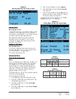
Refrigerant High Pressure Alarm
When the wall-mount unit receives a signal from the
compressor control module (CCM) indicating a high
pressure event, the wall-mount unit will generate an
alarm. Upon receiving the alarm, the wall-mount unit
will remove the “Y” call from the CCM, resetting the
status of the CCM. The alarm will stay present on the
wall-mount unit until manually cleared with TEC-EYE
hand-held diagnostic tool.
In addition to the CCM, the discharge pressure
transducer is used to prevent a high pressure event.
When the discharge pressure is above the discharge
pressure alarm setpoint (set 30 pounds below high
pressure switch, which is 650), the system will disable
stage 2 of mechanical cooling.
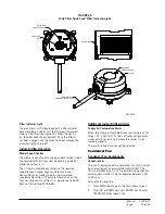
Phase Monitor
Used only on three phase equipment, the phase
monitor is a compressor protection device that will
prohibit operation of the compressor if the device senses
a possible reverse-rotation situation due to incorrect
phasing. On a call for compressor (and only compressor),
the device will check incoming phase, check for severe
voltage imbalance and check for proper frequency.
Under nominal conditions, a green LED light will show
on the face of the monitor. If there is improper phasing,
voltage imbalance or frequency deviation, the device will
show a red LED light and prohibit compressor operation.
If a fault condition occurs, reverse two of the supply
leads to the unit.
Do not reverse any of the unit factory
wires as damage may occur.
Compressor Operation
The compressor will be enabled when the unit (in
orphan mode) or LC provide a cooling stage 1 call. The
compressor call from the controller has several delays
that may affect the start or stop time of the compressor
in regards to the cooling demand. The compressor has
a minimum on time of 180 seconds to prevent short
cycling the compressor. The compressor also has a
minimum off time of 120 seconds to prevent start
ups before the pressure in the refrigeration system
equalizes. When the second stage is engaged, it also
has a minimum run time of 120 seconds to allow the
system to stabilize before returning to single stage or
shutting down.


