Manual 2100-671
Page
12 of 44
Exporting 7 Day Logs
See latest version of Supplemental Instructions manual
7960-826 for information on exporting 7 day I/O logs.
Exporting Parameters
See latest version of Supplemental Instructions manual
7960-827 for information on exporting parameters.
Zone
When paired with a supervisory controller that uses
zones to control groups of wall units, this unit uses the
zone setting to relay to the supervisory controller what
zone it is set to operate in. Up to three zones can be
established with up to 14 units in a single zone. (The
LC6000 supervisory controller can control up to a total
of 14 units.)
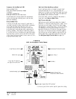
To change the zone:
1. Press MENU key to access the Main Menu screen.
2. Press UP or DOWN keys and ENTER key to enter
TECHNICIAN password 1313.
3. Press UP or DOWN keys to scroll to
Sys Config
;
press ENTER key.
4. Press UP or DOWN keys to scroll to
Unit Setup A1
screen.
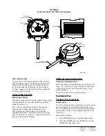
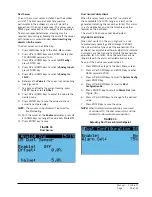
5. Press ENTER key to scroll to
Zone (
see Figure 11).
6. Press UP or DOWN keys to change to the desired
value (1, 2 or 3).
7. Press ENTER key to save value.
This sensor can be verified and adjusted by:
1. Press MENU key to go to the Main Menu screen.
2. Press UP or DOWN keys and ENTER key to enter
TECHNICIAN password 1313.
3. Press UP or DOWN keys to scroll to
I/O Config
;
press ENTER key.
4. Press UP or DOWN keys to scroll to
Analog Inputs
;
press ENTER key.
5. Press UP or DOWN keys to scroll to
Analog Ins 1/19
.
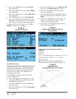
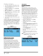
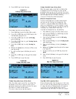
6. Verify the measurement displayed on screen is
accurate (see Figure 12).
7. If the measurement needs to be adjusted, apply an
offset value by pressing ENTER to scroll to
Offset
.
8. Press UP or DOWN keys to adjust the offset.
9. The update will not take effect until the cursor is
moved out of the
Offset
parameter.
10. Once adjusted, press the ESCAPE key several
times to return to Main Menu screen.
Temperature Control
Temperature Control Components
Return Air Temperature Sensor
The unit is equipped with a return air temperature
sensor to monitor the space temperature when the unit
is in orphan mode. The return air sensor is located
in the upper part of the return opening in such a way
that it is exposed to the entering airstream. An alarm
signal will be sent to the LC controller if the return air
temperature sensor is disconnected. The temperature is
measured with a 10k ohm NTC thermistor.
Return Air Temperature Alarm
When the return air temperature sensor value is out of
range (-41.0 to 303.0°F), the controller will generate
a sensor failure alarm to indicate the sensor is not
working properly.
This alarm is fixed and cannot be adjusted.
Temperature Control Operation
The unit utilizes differentials while in orphan mode to
control the space temperature. The differential values
all reference the setpoint therefore allowing the control
band to be easily changed using the setpoint. To change
specific staging characteristics, each differential can
be modified individually. There are separate setpoints
and differentials for cooling and heating. Specific to
the cooling differentials, the economizer will always be
utilized first on a cooling call unless outdoor conditions
are not acceptable for free cooling. In this case, the
compressor will be activated at stage 1 in place of the
economizer. All remaining stages will be shifted until
the economizer becomes available again.
FIGURE 11
Changing Zone
FIGURE 12
Adjusting Return Air Temperature Sensor


