background image

Random Access Adjustment Mode

8-2

5975618A RETRO BLOCK GRAPHICS 2100LC 240898

FILE SERVICE

LOAD

EDIT

RENAME

COPY

DELETE

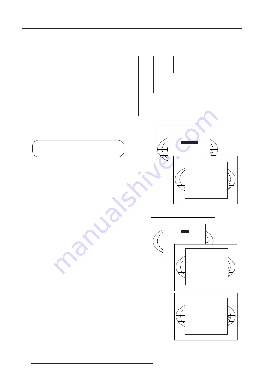
File Service

Before using a new source, a correct file has to be installed.  The

projector's memory contains a list of files corresponding to the most

used sources.  When the new source corresponds with one of these

files, the file can be loaded and saved for future use.  When there

is a little difference, the file can also be loaded and than edited until

the source specs are reached.

File annotation :

xxxxxxxx.xxx  x  xxxxXxxxxi

i or blank : i = interlaced, blank = not

interlaced

  xxxxXxxxx : active pixel rating

x : source number

xxx : file extension, first character is C (for custom

made files) or S (for standard files).  The second and

third character is used for a following number (=file

index)

file index for custom files : 00 to 63.

xxxxxxxx : base name,  8 characters.

Highlight 

File Service

 by pushing the control disk up or down and

press 

ENTER

 to select. The File service menu will be displayed.

ENTER

 displays the File Service menu.

EXIT

 returns to the Path selection menu.

ADJUST

 returns to operational mode.

The following file manipulations are possible :

- Load : installation of a file for a new source.

- Edit : editing a loaded file to the source specs.

- Rename : renaming a file.

- Copy : copying a file to a new file.

- Delete :  deleting an existing file.

- Options : way of sorting the files.

Load File

Push the control disk up or down to select LOAD and press 

ENTER

to display the Load menu.

The Load menu displays the corresponding files depending on the

installed filter.

This filter can be 'Fit' or 'All'.  To change the filter, push the control disk

to the right to select  'Filter List' ('Filter List' will be highlighted) and

press 

ENTER

 to toggle the annotation between brackets.

'All' : all files that can be loaded will be displayed.

'Fit' : only the best fitting files will  be displayed

Push the control disk up or down to select the most fitting file and press

ENTER

 to select.

When scrolling through the files, the image will be adapted according

to the settings of the selected file (on line adaptation).  When the best

fitting image is displayed, press 

ENTER

 to select this file.  A 'Confirm

Load file' menu will display the newly created file and the file on which

the new file is based.

Press 

ENTER

 to confirm your new creations or 

EXIT

 to return to the

load file menu.

If the displayed image is not yet as it should be, select the most

corresponding file and go to the Edit menu to change the file settings.

During a load file, the actual active file is displayed next to the

indication 'Active file'.

RANDOM ACCESS

ADJUSTMENT MODE

FILE SERVICE

PICTURE TUNING

AUDIO TUNING

GEOMETRY

FILE SERVICE

LOAD

EDIT

RENAME

COPY

DELETE

OPTIONS

Select with 

ê

 or 

é

then <ENTER>

<EXIT> to return.

CONFIRM

LOAD FILE

Create file

ntsc.c02

based on file

ntsc.s01?

<ENTER> to confirm

<EXIT> to return

LOAD FILE

FILTER LIST [All]

Filename

Src

Resolution

-----------------------------------------------------

ntsc.s01

1

675x240i

ntsc.c01

1

675x240i

ntsc_2.s01 1

675x240i

-----------------------------------------------------

Active file : ntsc.c50

Select with 

ê

é 

or 

è

<ENTER> to accept

<EXIT> to return.

Summary of Contents for RETRO DATA 2100LC

Page 1: ...OWNER S MANUAL RETRO BLOCK GRAPHICS 2100LC R9031278 ...

Page 2: ...BARCO PROJECTION SYSTEMS Rev02 RETRO BLOCK GRAPHICS OWNER S MANUAL Date 250898 2100LC R9031278 Art No R5975618A ...

Page 3: ...armful interference to radio communications Operation of this equipment in a residential area is likely to cause harmful interference in which case the user will be required to correct the interference at his own expense Note The use of shielded cables is required to comply within the limits of Part 15 of FCC rules and EN55022 All the safety and operating instructions should be read before using t...

Page 4: ...necting a Computer e g IBM PC or compatible Apple Macintosh to the RS 232 Input of the Projector 5 3 Set up of the Baud Rate for Communication with a Computer 5 4 Connecting a RCVDS 05 to the Projector 5 4 Connecting a VS05 to the Projector 5 4 Connecting an IR Remote Receiver 800 to the Projector 5 4 CONTROLLING 6 1 How to Use the RCU 6 1 Projector Address 6 1 How to Display a Projector Address 6...

Page 5: ... 3 Change Language 10 3 Change Projector Address 10 3 Change Baudrate PC 10 4 Reset Lamp Runtime 10 4 Lamp Run Time History 10 4 Lamp Drive Mode 10 5 Barco Logo 10 5 Preset Input Balance 10 5 60 Hz Tracking 10 6 I2C Diagnosis 10 6 APPENDIXA STANDARD SOURCE SET UP FILES A 1 APPENDIX B LENSES B 1 Focusing the Lens B 1 Lens Cleaning Procedure B 1 Lenses B 2 APPENDIX C SOURCE NUMBERS 90 99 C 1 APPENDI...

Page 6: ...l they will come in handy if you ever have to ship your projector For maximum protection re pack your projector as it was originally packed in the factory see drawing below Contents of the shipped box 1RETROBLOCKGRAPHICS2100LC 1 remote control unit 1 9V battery 1 power cable with outlet plug type ANSI 73 11 3 plastic supporting feet 4 plastic handles 1 owners manual 1 installation manual 1 safety ...

Page 7: ...the battery cover on the backside of the remote control by pushing the indicated handle a little to the bottom of the RCU Lift up the top side of the cover at the same time fig 1 Insert the new 9 V battery in the lower compartment and connect the battery to the contact plate Put the cover back on Note the projector address has to be programmed on the RCU before using the RCU see chapter Controllin...

Page 8: ...the Installation menu EXIT returns to operational mode ENTER to confirm the selection EXIT returns to the installation menu ADJUST returns to operational mode Highlight Configuration by pushing the control disk forward or backward and press ENTER to select The configuration menu will be displayed ENTER displays the Configuration menu EXIT returns to the path selection menu ADJUST returns to operat...

Page 9: ...hift of the image Lower bolt Allows a limited horizontal shift of the image 15 RS 232 IN To allow communication with external computer e g IBM PC or compatible Macintosh 03 Audio Out 2 x Cinch RCA stereo audio output 04 Audio Select LED s Lit up next to each audio input when AUDIO IN A B C or AUDIO OUT are selected 05 Audio In 3 audio inputs on 2 Cinch RCA connectors for audio L R 06 Port 3 S Vide...

Page 10: ...ows communication with the 800 series peripherals 18 CTRL Remote input for hard wired remote control 19 Lens Mounting Projected picture output Control Panel Terminology a Local Keypad The keypad is located on the top of the projector b Remote Control 20 IR Receiver IR receiving sensor 21 Discrete Off axis Mechanical adaptation of lens mounting to chosen internal conversion kit Range from on axis p...

Page 11: ...is retained for immediate restarting 07 TEXT When adjusting one of the image controls during a meeting the displayed bar scale can be removed by pressing TEXT key first To re display the bar scale on the screen press TEXT key again TEXT key is only active in operational mode When TEXT is off no warning message will be displayed 08 Picture Controls Use these buttons to obtain the desired level see ...

Page 12: ...alified service technician to adapt the input voltage to the correct voltage on the wall outlet When the projector leaves the factory it is pre configured to operate on a mains power input of 120 Vac This projector may be connected to an IT power system 8 2 1 8 2 1 8 2 1 9 2 9 2 6 9 2 5 9 5 9 5 5 5 5 5 5 5 9 9 3257 3257 3257 3257 3257 56 287 56 1 200 3257 75 hard wire remote 8 2 287 8 2 1 8 2 1 8 ...

Page 13: ...G LAMP RUN TIME 20 hours Lamp Lifetime Before the end of lamp life the following message will be scrolling over the screen several times It will be displayed at the following points in time end of lamp life 500 hours end of lamp life 100 hours end of lamp life 50 hours end of lamp life Press EXIT to remove the message The total lamp lifetime of the lamp for a safe operation is 4000 hours max in no...

Page 14: ...coder etc 1 x BNC 1 0Vpp 3 dB Connect the audio input signals to the AUDIO A input when the audio lock is OFF see also chapter Controlling Video Input Selection Press digit button 1 on the RCU RGB with separate sync composite or hor or vert sync sync signals on green tri level sync or composite video as sync signal Source input Input type Digit button on RCU Audio Input lock is off port 1 Comp Vid...

Page 15: ... etc 1 x Cinch RCA 1 0Vpp 3 dB Connect the audio input signals to the AUDIO B input when the audio lock is OFF see also chapter Controlling Video input selection Press digit button 2 on the RCU Connecting a S Video Source to the 4 pin mini DIN Input port 3 Separate Y luma C chroma signals for higher quality playback of Super VHS signals 1 x 4 pins plug pin configuration 1 ground luminance 2 ground...

Page 16: ...0 MAGIK interface Order number 120V R9828129 Order number 230V R9828120 RGBS RGsB analog 5 x BNC Red 0 7 Vpp 3 dB Blue 0 7 Vpp 3 dB Green 0 7 Vpp 3 dB 1 Vpp 3 dB if sync on green Vert sync 1 Vpp to 4 Vpp 3 dB Hor sync Composite sync 1 Vpp to 4 Vpp 3 dB All inputs are non floating inputs All input signals are 75 ohm terminated Connect the possible audio input signals for input 4 to the AUDIO B inpu...

Page 17: ... VS05 can switch up to 5 Composite Video sources 3 Super Video sources and 1 RGB analog or component video source to the projector In addition the audio signal related to the source can be switched to an audio amplifier To do so connect the audio signal of the source to the Audio Input A Order number R9827890 For more information about the use of the VS05 consult the VS05 Owner s Manual BARCO orde...

Page 18: ... 255 which can be set in the Service mode Only projectors with addresses between 0 and 9 can be controlled with the RCU b How to Control the Projector or Projectors The projector s address may be set to any value between 0 and 255 When the address is set the projector can be controlled now RCU for addresses between 0 and 9 Computer e g IBM PC or compatible Apple MAC etc for addresses between 0 and...

Page 19: ...example screen The length of the bar scale and the value of the numeric indication indicate the current memory setting for this source The bar scale changes as the or buttons of the control on the RCU are pressed or the or buttons on the local keypad Brightness Control A correct brightness setting is important for good image reproduc tion Use the button for a higher brightness Use the button for a...

Page 20: ...n the left speaker than on the right one The Pause Key When the Pause key is pressed the image projection is stopped but the projector remains with full power for immediate restart The sound is not interrupted To restart the image reproduction press pause key press exit key or select a source number The Mute Key When the Mute key is pressed the sound reproduction is stopped The image is still disp...

Page 21: ...nformation Some items in the Adjustment mode are password protected While selecting such an item the projector asks to enter your password Password protection is only available when the password strap on the controller module is ON see Change Password in chapter Service Mode Your password contains 4 digits Enter the digits with the numeric keys Example 2 3 1 9 The first digit position is highlight...

Page 22: ... or down to highlight Random Access and then press ENTER RANDOMACCESS ADJUSTMENTMODE LOAD EDIT RENAME COPY OPTIONS DELETE SYNC COLORBALANCE GAMMA STILLVIDEO VOLUME BASS TREBLE BALANCE MUTE FILESERVICE PICTURETUNING LOCK FADE GEOMETRY AUDIOTUNING ADJUSTMENT MODE Select a path from below RANDOM ACCESS INSTALLATION SERVICE Source 01 Select with ê or é then ENTER EXIT to return SHIFT ...

Page 23: ... down to select LOAD and press ENTER to display the Load menu The Load menu displays the corresponding files depending on the installed filter This filter can be Fit or All To change the filter push the control disk to the right to select Filter List Filter List will be highlighted and press ENTER to toggle the annotation between brackets All all files that can be loaded will be displayed Fit only...

Page 24: ...r down to select an item The color of the selected item will change and follow one of the three methods to change the value a Press ENTER to activate the digits and enter directly with the numeric keys on the RCU or local keypad the new value or b Press ENTER to activate the digits Push the control disk to the right or to the left to select the changing digit Push the control disk up or down to sc...

Page 25: ... Change the value by pushing the control stick to the left or to the right Field polarity Default auto auto autodetection of the field polarity The field polarity function is used for interlaced images Both rasters of the image could be shifted in a wrong way double lines are visilble in the image This can be corrected by forcing the field polarity to neg or pos Use the ENTER key to toggle between...

Page 26: ...ktoselectRENAMEandpressENTER TheRename selection menu will be displayed Use the control disk to select a file name and press ENTER to select The Rename menu will be displayed with the selected file name already filled in in the From file name area and in the To file name area The first character is highlighted Push the control disk to the right or to the left to select the desired character Change...

Page 27: ...NG SYNC SLOW STILL VIDEO ON COLOR BALANCE GAMMA Select with ê or é then ENTER EXIT to return Push the control disk up or down to select a file and press ENTER If All is selected your password has to be entered before all files will be deleted A confirmation menu Delete file file name is displayed When you want to delete the file press ENTER If you do not want to delete the file press EXIT Note tha...

Page 28: ...disk up or down and press ENTER to toggle between ON and OFF Still Video ON the displayed image contains less jitter and gives a sharper image Still Video OFF for moving picture Color Balance Highlight Color Balance by pushing the control disk up or down and press ENTER to select the color balance selection menu The next choices are possible Fixed color balance 3200 K reddish 6500 K white 9300 K b...

Page 29: ...ill be reproduced independent the selected input source Lock input b the sound corresponding to audio b input will be reproduced independent the selected input source Lock input c the sound corresponding to audio c input will be reproduced independent the selected input source Highlight Audio Tuning by pushing the control disk up or down and press ENTER to select The Audio Tuning menu will be disp...

Page 30: ...icated value and enter the desired value with the digit keys Press ENTER to confirm the entered value Shift The image can be shifted in a horizontal or vertical direction Push the control disk up or down to shift the image in a vertical direction Push the control disk to the right or to the left to shift the image in a horizontal direction The default value for the shift is 0 Shifting in a vertica...

Page 31: ...to display the Internal Pattern selection menu The following test pattern are available Outline Hatch Color Bars Multiburst Checker Board Purity Page Char Alpha numeric Char Each pattern except Purity can be inverted by pressing ENTER To return to the normal pattern press EXIT ADJUSTMENT MODE Select a path from below RANDOM ACCESS INSTALLATION SERVICE INSTALLATION CONFIGURATION OSD COLOR INTERNAL ...

Page 32: ...AIS Select with ê or é then ENTER EXIT to return CHANGE PROJ ADDRESS Enter new address 001 Select with ç or è Reprogram with ê or é or numeric keys ENTER to confirm EXIT to return CHANGE BAUDRATE PC 9600 4800 2400 1200 600 300 150 75 Select with ê or é ENTER to accept EXIT to return WARNING RISK OF ELECTRICAL SHOCK RESET LAMP RUN TIME is reserved to qualified service personnel ENTER to continue EX...

Page 33: ...tion possible installations Front Ceiling Front Table Rear Ceiling Rear Table To change the installation configuration follow the instructions in chapter Installation Set Up Baud rate transfer speed for communication with a IBM PC or compatible or MAC The baud rate of the projector must be the same as the baud rate of the connected computer When there is a difference consult Change Baudrate PC in ...

Page 34: ...rd Press EXIT if no changes have to be made Change Projector Address Every projector requires an individual address between 0 and 255 This address can be software installed To change that address push the control disc up or down to highlight Change Proj Address and press ENTER The Change Projector Address menu will be displayed and the actual address will be filled in The first digit is highlighte...

Page 35: ...y by pushing the control disc up or down and press ENTER A listing with the lamp serial number and the corresponding run time will be displayed The actual installed lamp will be marked Press ENTER to have more details Press EXIT to return to the service mode selection menu CHANGE BAUDRATE PC 9600 4800 2400 1200 600 300 150 75 Select with ê or é ENTER to accept EXIT to return WARNING RISK OF ELECTR...

Page 36: ...g the control disk s up down selectors and then press ENTER to select Using the control disk the BARCO LOGO can now be moved around the screen Hot key OFF TEXT Highlight using the control disk s up down selectorsandthenpress ENTERtotogglebetweenOFF TEXT When TEXT is chosen the BARCO LOGO can be displayed or hidden using the TEXT key on the RCU or the local keypad Only if status is ON Press EXIT to...

Page 37: ...R SAA7151B 8AH DECODER SAA7152 B2H DECODER SAA7192A E0H EXIT TO RETURN 60 Hz Tracking 60 Hz tracking is used to adjust the 60 Hz by sychronous signals Highlight 60 Hz Tracking by pushing the control disk up or down and press ENTER When 60 Hz Tracking is selected in the Service Mode selection menu the following warning will be displayed 60 Hz Tracking is reserved to qualified service personnel If y...

Page 38: ...5 13 500 864 720 313 278 SECAM_3 675 X 278I 25 000 15 625 13 500 864 720 313 278 EGA 640 X 350 59 702 21 851 16 257 744 640 366 350 MAC_5 512 X 342 60 158 22 259 15 670 704 512 370 342 MAC_3 512 X 384 60 147 24 480 15 667 640 512 407 384 MAC_4 560 X 384 60 147 24 480 17 234 704 560 407 384 8514 A 1024 X 384I 43 479 35 522 44 900 1264 1024 409 384 VGA_TXT 720 X 400 70 087 31 469 28 322 900 720 449 ...

Page 39: ...32 1260 960 720 680 ED 735 X 480 59 940 31 470 27 000 910 735 525 480 PC98_1 640 X 400 56 416 24 823 21 050 848 640 440 400 PC98_2 1120 X 375I 79 987 32 835 47 840 1457 1120 411 375 PC98_3 1120 X 750 60 000 50 000 78 569 1571 1120 833 750 MAC_6 832 X 624 74 550 49 722 57 280 1152 832 667 624 MAC_7 1024 X 768 74 910 60 150 80 000 1330 1024 803 768 PAM500 640 X 400 60 000 26 400 22 810 864 840 440 4...

Page 40: ...e SD lens without using a TorayseeTM cloth To minimize the possibility of damaging the optical coating or scratch ing exposed lens surfaces we have developed recommendations for cleaning lenses FIRST we recommend you try to remove any material from the lens by blowing it off with deionized air or lightly brushing it with a soft camel s hair brush Plastic lens with multilayer coatings all glass len...

Page 41: ...x SW 33 5 376 6 SW QSD 1 2 1 Metric PD 1 2098 x SW 0 2543 0 0894 SW Inch PD 1 2098 x SW 10 3 44 SW Lenses This APPENDIX gives an overview of the tables and formulas for the available lenses for the projector The next lenses are available Name length lens diam lens weight order number mm inch mm inch kg lbs QSD 0 8 1 210 8 27 min 110 4 33 3 71 8 18 R9829640 max 186 7 32 SD 1 15 1 124 4 88 min 110 4...

Page 42: ...ow to create a second file for sources 0 to 5 1 Select the source between 0 and 5 2 Select the corresponding source number between 81 and 85 or 91 and 95 with the digit keys on the RCU 3 Enter the adjustment mode and load a corresponding file Edit this file if necessary 4 Save the file and exit the adjustment mode Projector with a 800 Peripheral Connected Source numbers 91 99 These source numbers ...

Page 43: ...espond to the physical inputs 1 5 of the projector e g When slot 1 of the projector has to be selected key in source number 81 The relationship between the sources of slot 1 5 of the projector with the 800 peripheral is shown below source of slot 1 source number 81 source of slot 2 source number 82 source of slot 3 source number 83 source of slot 4 source number 84 source of slot 5 source number 8...

Page 44: ...he dust filters the following steps have to be followed Remove the fixing screw for the holder of the dust filter you want to replace indicated with respectively A and B Gently pull the holder in the indicated direction black arrow Remove the old dust filter and place the new one in Place back the dust filter holder by sliding it under the hooking sleeves Place back and tighten the fixing screw Re...

Page 45: ...h the projector 3 plastic feet 4 plastic handles Plastic feet These feet can be used in a front table configuration to protect the table and to make small adjustments to the position of the projector They have to be fixed on the bottom of the projector Plastic handles These handles can be used to ease transportation of the projector They can be fixed on the indicated places ...

Page 46: ...CARD RCU 3 3 5 8 352 725 1387 6 7 21 6285 1387 6285 6 5 9 6 9LGHR 1 9LGHR LQFK 6 9LGHR 5 6 9 5 6 9 5 8 5 8 5 8 352 725 352 725 352 725 1387 6285 6 1387 6285 6 1387 6285 6 1387 6285 6 1387 6 7 21 6285 5 9 6 5 9 6 1387 6285 6 5 9 6 9LGHR 1 9LGHR LQFK 6 9LGHR 5 6 9 5 6 9 ...

Reviews: