24-1701050-00 /01
EC-200 to EC-210 Conversion Kit
27
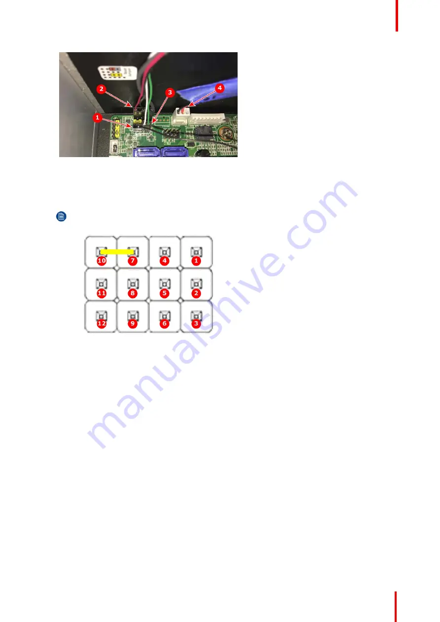
Image 2-28: Motherboard connections: reset, power button, power-button LED, and rear unit fan
1
Reset connection from right-side keyboard
2
Power button LED connection
3
Power button connection
4
Rear unit fan at SYSFAN2
Note:
For Step 8 and Step 9 refer to Image 2-28 and to Image 2-29.
Image 2-29: JFP1 pinout
1
Pin 1: +5V
2
Pin 2: HDD LED+
3
Pin 3: Power
4
Pin 4: SPK_P2
5
Pin 5: HDD LED
–
6
Pin 6: Power button
–
7
Pin 7: SPK_P3
8
Pin 8: SMB_Data
9
Pin 9: System reset+
10
Pin 10: SPK_P4
11
Pin 11: SMB_CLK
12
Pin 12: System reset
–
8.
Connect the black reset line (2-pin connector) to JFP1.
Make the connection so that the black wire is connected to pin 9 of JFP1.
9.
Connect the power-button cable (2-pin connector on 90409634EF) to pins 3 and 6 of JFP1.
Make the connection so that the green wire is connected to pin 3 and the white wire is connected to pin 6.
10.
Connect the USB to left side of keyboard (white USB cable) to the second port from the bottom at USB561112.
11.
Connect the power supply to the motherboard at EATXPWR1.
12.
Connect the auxiliary power to the motherboard at ATX12V1.


