


24-1701050-00 /01
EC-200 to EC-210 Conversion Kit
17
Image 2-7: Rear view of touchscreen assembly, showing touchcreen interface boards
1
Breakout board
2
RS-232 interface (harness) board
5.
Remove the touchscreen assembly from the EC-200 unit.
Note:
After the screen assembly is removed, access holes for three of the motherboard screws can be
seen in the support bar that runs the width of the unit.
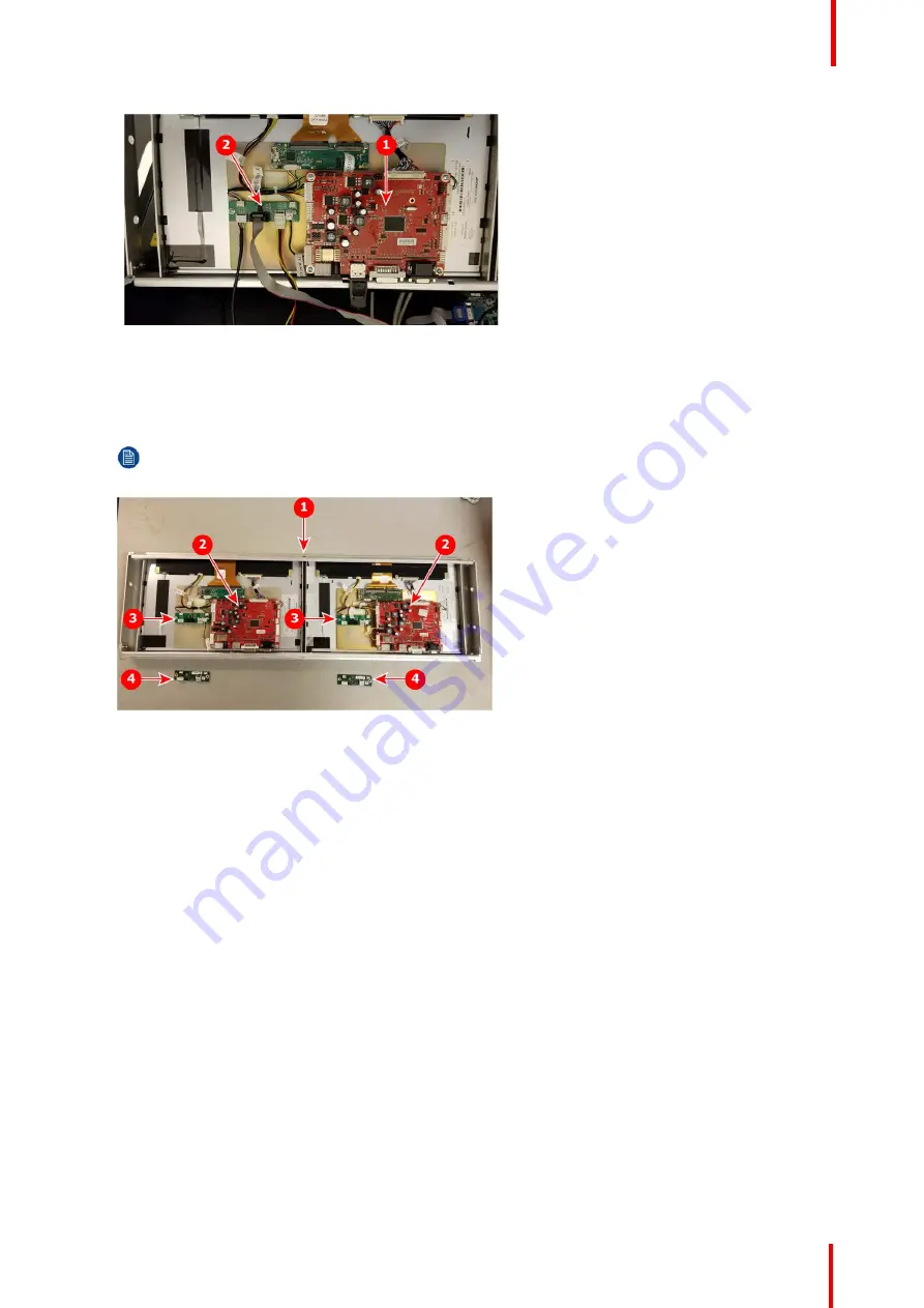
Image 2-8: Rear view of screen assembly, showing touchcreen interface boards
1
Touchscreen assembly (rear)
2
Breakout board
3
RS-232 interface board (EC-200)
4
USB interface board (EC-210)
6.
Carefully disconnect the connectors that are attached to the RS-232 interface board on the rear right-side
display.
7.
Remove the screws that attach the RS-232 interface board (green board to side of the larger, red break-out
board) to the back of screen assembly.
Use a T10 Torx driver (or a 1/16
”
Allen wrench) to remove the two screws. (Older systems have two Phillips
screws.) The two screws will be used to install the new EC-210 USB interface board.
8.
Install the USB interface board, provided in the EC-210 upgrade kit, in the location where you just removed the
EC-200 RS-232 interface board.
Make sure the board is in the correct orientation. You can reference the left-side RS-232 interface board to
verify the correct orientation.
Screw the board into place using the two screws removed in the previous step.
Refer to Image 2-9 for Step 7 through Step 9.


