


Installation
Barco - OV-708/OV-713/OV-715– R59770137 – installation manual – revision 01– September 2007 ________________________________
________________________________
________________________________
_______________________________________________
_______________
_______________
_______________ 33
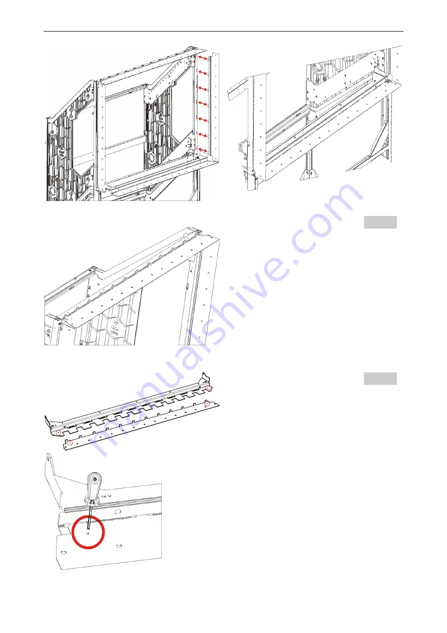
Step 36
Hook the stitch plates R856317 and R856318 (top
row) into each other (R856549 and R856525).
Step 37
Use a pin or a screw or a screw driver to temporarily
lock all horizontal stitch plates to their nominal
position indicated by the reference hole (4mm)
Unlock them only when the screen is mounted and
stitched!
Summary of Contents for OV-708
Page 1: ...Installation manual OV 708 OV 713 OV 715 R59770137...
Page 15: ......


