background image

System manual MeDis 5MP1HM

93

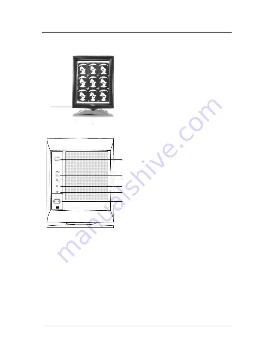
Controls and connectors

1

REMOTE OUT

REMOTE IN

VIDEO

HS / CS

VS

2

4

5

6

7

8

9
10
11

3

{1}

Optical sensor plug

{2}

Ambient Light Compensation

(ALC) sensor (optional)

{3}

Green power LED

{4}

Control knob, combination of a

push button and a turning

knob.

The control knob is used for

switching the power on/off, and

selecting and performing

functions in the OSD (on-

screen display) menu.

{5}

Remote (RS-232) output

{6}

Remote (RS-232) input

{7}

Video input

{8}

Horizontal / composite sync.

input

{9}

Vertical sync. input

{10}

Power input

{11}

Power button

Display User Manual

Summary of Contents for MeDis 5MP1HM

Page 1: ...MEDIS 5MP1HM System Manual...

Page 2: ...E mail sales medical barco com http www barcoview com BarcoView Inc 3059 Premiere Parkway Duluth Georgia 30097 USA Phone 1 678 475 8000 Fax 1 678 475 8100 E mail sales medical barco com http www barc...

Page 3: ...urself With the 5MP1HM 15 Jumper Location 15 Using the VGA Capabilities of the BarcoMed 5MP1HM 15 Examples of PCI Slots 16 Installing the BarcoMed 5MP1HM Display Controller 17 Running Multiple BarcoMe...

Page 4: ...your BarcoMed 5MP2 AURA 5MP2 5MP1HM 5MP1H or 4MP2 Drivers 53 Barcomed controller tools 55 BarcoMed Driver Tab 57 Introduction 57 Status 59 Graphics Board 59 Driver Version 59 Resolution 59 Palette Mo...

Page 5: ...tware installation and usage 81 MediCal software installation 83 Optical sensor connection 83 Using MediCal 83 Display user manual 85 Introduction 89 Overview 89 Resolution and bandwidths 89 The memor...

Page 6: ...y 103 Settings 103 Adjustments 105 a How to make the adjustments 105 b Description of the adjustments 105 Geometry 105 Focus 111 ALC optional 111 Luminance uniformity 112 Factory reset 112 c How to sa...

Page 7: ...System manual MeDis 5MP1HM 7 INTRODUCTION...

Page 8: ...System manual MeDis 5MP1HM 8 This page intentionally left blank Introduction...

Page 9: ...t correspond to the list Other relevant documents MediCal Pro Installation and User Manual MeDis installation overview To install the MeDis system completely you have to follow these steps 1 Install t...

Page 10: ...System manual MeDis 5MP1HM 10 This page intentionally left blank Introduction...

Page 11: ...System manual MeDis 5MP1HM 11 DISPLAY CONTROLLER INSTALLATION...

Page 12: ...System manual MeDis 5MP1HM 12 This page intentionally left blank Display Controller installation...

Page 13: ...tion Single slot PCI card Display Properties Control Panel to dynamically change display settings Control Panel support for the English U S Dutch German Japanese Korean Simplified Chinese and Traditio...

Page 14: ...System manual MeDis 5MP1HM 14 This page intentionally left blank Display Controller installation...

Page 15: ...r Figure 1 The 5MP1HM Display Controller Jumper Location There is one user settable jumper on the BarcoMed 5MP1HM It is used to enable or disable the VGA capabilities of the controller Using the VGA C...

Page 16: ...igure 2 VGA Jumper Enlarged View NOTE To use multiple 5MP1HM controllers in a single host with VGA enabled you need to enable VGA on only ONE of the 5MP1HM controllers and disable VGA on ALL other Bar...

Page 17: ...free 64 bit PCI slot see Figure 3 for examples of slots Be sure that the controller is seated firmly in the slot 5 Secure the card to the chassis with the PC s I O panel mounting screw and replace th...

Page 18: ...c n e e r g o e d i V e h t t c e n n o C e r e h S H t s 1 e h t r o f r o t c e n n o c k c a l B c n y S l a t n o z i r o H e h t t c e n n o C e r e h y a l p s i d S V t s 1 e h t r o f r o t c...

Page 19: ...System manual MeDis 5MP1HM 19 DISPLAY INSTALLATION...

Page 20: ...System manual MeDis 5MP1HM 20 This page intentionally left blank Display installation...

Page 21: ...take a good look at the figures and then read the rest of the text very carefully 1 2 Display 1 rear view Display 2 rear view Video cable 1 Video cable 2 Remote cable Remote cable PC Video cable from...

Page 22: ...umber on a label on the cable The cable number must correspond to the head on the display controller and the display it is connected to E g cable 1 must connect head 1 on the first display controller...

Page 23: ...he port has 25 pins use the D25 to D9 interface you find in the MediCal software box to connect the remote cable Plug the other end the D9 male connector into the Remote In connector on one of the MGD...

Page 24: ...System manual MeDis 5MP1HM 24 This page intentionally left blank Display installation...

Page 25: ...System manual MeDis 5MP1HM 25 BARCOMED DRIVER AND SOFTWARE INSTALLATION...

Page 26: ...System manual MeDis 5MP1HM 26 This page intentionally left blank BarcoMed driver and software installation...

Page 27: ...l P d n a g u l P A R U A 2 P M 5 w e i V o c r a B A R U A o e d i V r e l l o r t n o C o e d i V A G V r e l l o r t n o C r o e l b i t a p m o C A R U A 2 P M 5 d e M o c r a B 2 P M 5 e n i g a...

Page 28: ...carefully note which PCI slot each board is in and then install the drivers for each type of board based on the PCI slot they are installed in If you are using the VGA Capabilities of a BarcoMed Imagi...

Page 29: ...drivers or installing a new driver release over an existing driver release skip to the step 5 1 Install the BarcoMed Display Controller s into your machine Please refer to the Hardware Installation G...

Page 30: ...nstalled the new version of the Microsoft Installer click OK to continue The BarcoMed Product Installation Wizard may prompt you to restart your system If it does click Yes to restart your system When...

Page 31: ...vices the dialog box will be empty and program will exit when the user clicks Finish or Cancel Select the device you want to install and then click Next Note You can install the driver for only one ty...

Page 32: ...abled or not DualView allows a dual head display controller to display two separate desktops one for each display instead of a single virtual desktop that spans across both displays DualView is a feat...

Page 33: ...election click Back to return to the Device Selection Screen Click Next to begin installing the driver Click Cancel to abort the driver installation Special Note Once you click Next you cannot cancel...

Page 34: ...he BarcoMed Product Install Wizard The wizard will now begin installing the next selected piece of BarcoMed Software If you do not want to install the other BarcoMed Software until after you have inst...

Page 35: ...llShield Wizard to begin the installation Click Cancel to cancel the DPMS installation and return to the BarcoMed Product Install Wizard 16 The Customer Information screen will appear see figure 13 on...

Page 36: ...are not supported in the Japanese Korean and Chinese languages We recommend that the users of these three languages install the English default schemes and then rename and save them into their langua...

Page 37: ...ed installing your BarcoMed Software click Finish to exit the BarcoMed Product Install Wizard or click Back to return to the Welcome Screen of the BarcoMed Product Install Wizard to select additional...

Page 38: ...he Adapter tab and then click on the List All Modes button Select the desired resolution from the list and click OK The chart on the next page contains a partial list of the possible Windows virtual d...

Page 39: ...s 0 6 5 2 x 8 4 0 2 0 6 5 2 x 6 9 0 4 A R U A 2 P M 5 e n O a n i s y a l p s i d 2 n m u l o c e l g n i s 0 6 5 2 x 8 4 0 2 0 2 1 5 x 8 4 0 2 M H 1 P M 5 e n O H 1 P M 5 r o y a l p s i d 1 0 6 5 2...

Page 40: ...r BarcoMed 5MP2 AURA 5MP2 5MP1HM 5MP1H or 4MP2 Driver To reinstall or update only the BarcoMed Driver follow the steps described in the section Using the BarcoMed Product Installation Wizard found at...

Page 41: ...our BarcoMed 5MP Family Display Controllers unless you are using the VGA capabilities of one of your board then Windows XP will load the default Microsoft VGA driver for that board d e M o c r a B d r...

Page 42: ...ntify the BarcoMed Display Controllers by their Video Chipset If you choose to install multiple types of BarcoMed Display Controllers in your computer it is important to carefully note which PCI slot...

Page 43: ...over an existing driver release skip to the step 7 on the next page 1 Install the BarcoMed Display Controller s into your machine Please refer to the Hardware Installation Guide that came with your B...

Page 44: ...deselect it by clearing the checkbox next to it Click Install to continue or Cancel to exit the wizard Figure 17 Driver Installation 9 Click Next on the Barco Device Driver Setup Wizard s Welcome Scr...

Page 45: ...n the one you are installing figure 18 Figure 18 Click OK to continue If you don t want to replace the exiting driver click OK and then click Cancel 12 If you are installing the BarcoMed 5MP1HM or 5MP...

Page 46: ...System manual MeDis 5MP1HM 46 Figure 19 5MP2 AURA DualView Enabled Figure 20 5MP2 AURA DualView Disabled BarcoMed driver and software installation...

Page 47: ...return to the Device Selection Screen Click Next to begin installing the driver Click Cancel to abort the driver installation Special Note Once you click Next you cannot cancel the driver installatio...

Page 48: ...k Cancel Then click Yes then click Finish and then click Back and try reinstalling the driver following the steps above or using the steps outlined in Reinstalling or Updating your BarcoMed Drivers se...

Page 49: ...ault schemes with either Dutch or German names Currently the default schemes are not supported in the Japanese Korean and Chinese languages We recommend that the users of these three languages install...

Page 50: ...zard will now display the screen shown in figure 25 below If you are finished installing your BarcoMed Software click Finish to exit the BarcoMed Product Install Wizard or click Back to return to the...

Page 51: ...T using the VGA capabilities of your BarcoMed Display Controller the display may not be enabled yet To enable the display check the Extend my Windows desktop onto this monitor checkbox Do not click th...

Page 52: ...indow on the Settings tab so that the arrangement in the window on the Settings tab matches the physical arrangement of your configuration Use the BarcoMed Driver Tab of the Display Properties Control...

Page 53: ...ion Using the BarcoMed Product Installation Wizard found at the beginning of this chapter with the following changes 1 Skip Step 1 2 In Step 8 clear the checkbox next to the BARCO DPMS 3 When the driv...

Page 54: ...System manual MeDis 5MP1HM 54 This page intentionally left blank BarcoMed driver and software installation...

Page 55: ...System manual MeDis 5MP1HM 55 BARCOMED CONTROLLER TOOLS...

Page 56: ...System manual MeDis 5MP1HM 56 This page intentionally left blank BarcoMed controller tools...

Page 57: ...Properties Control Panel by right clicking on the desktop then select Properties 2 Under Windows NT 4 0 Click on the BarcoMed Driver Tab see figure 27 below Under Windows 2000 click on Settings tab D...

Page 58: ...System manual MeDis 5MP1HM 58 Figure 28 BarcoMed Driver Tab under Windows 2000 Figure 29 BarcoMed Driver Tab under Windows XP BarcoMed controller tools...

Page 59: ...cture below this mode reserves the first 10 and last 10 entries in the palette for the Windows operating system but applications can manipulate the middle 236 entries This is the standard palette mode...

Page 60: ...is prevents palette conflicts between applications which can cause image color values to appear distorted in the background application As shown in the picture below each of the 256 entries in the pal...

Page 61: ...ed range of colors in an image at the cost of spatial resolution Adjacent pixels are assigned differing color values when viewed from a distance these colors seem to blend into a single intermediate c...

Page 62: ...set via the registry and it doesn t agree with any of the configurations that the display control panel supports Contact BarcoView Medical Imaging Systems for further information Languages supported...

Page 63: ...M 1 n o i t a m r o f n I e r a w m r i F d n a I C P H 2 P M 2 n o i t a m r o f n I e r a w m r i F d n a I C P P H 1 P M 2 n o i t a m r o f n I e r a w m r i F d n a I C P H F 2 P M 2 n o i t a m...

Page 64: ...der Windows NT 4 0 Click on the BarcoMed Hardware Tab see figure 30 below Under Windows 2000 and Windows XP click on the Settings tab Double click on the rectangle that represents the BarcoMed Display...

Page 65: ...indows XP Using The BarcoMed Hardware Tab Device Displays the current BarcoMed Display Controller driver and the currently selected display resolution Identify Device This button is for BarcoView Medi...

Page 66: ...n display more information about the BarcoMed Display Controller installed in the selected PCI slot Generate Report Button Clicking this button will produce two reports It will first run the Windows D...

Page 67: ...ash update procedure The user will be prompted to select a firmware update file to use for the update therefore you will need a firmware update file for your specific BarcoMed Display Controller in or...

Page 68: ...System manual MeDis 5MP1HM 68 This page intentionally left blank BarcoMed controller tools...

Page 69: ...splays require some warm up time before they are at full performance On CRT based displays such as the Barco MGD series a regular screen saver can be invoked during user inactivity during the work day...

Page 70: ...tes the scheme that is selected in the Scheme box Work Schedule In this part of the control panel the user may specify the Begin Work Day and End Work Day times for each work day If the system is not...

Page 71: ...mum power savings on CORONIS displays Available Savers Lists the Available Screen Savers Settings Changes settings for the selected screen saver DPMS Settings After Work Day If you have an display con...

Page 72: ...dor for this warm up time On Barco CORONIS displays the I GUARD will stabilize the image within a few seconds after the display returns to the active state so there is no need for a warm up time perio...

Page 73: ...uding those who do not have administrator privileges can create modify or delete private schemes When the delete button is pressed the user is asked to confirm the delete request Using the BARCO DPMS...

Page 74: ...System manual MeDis 5MP1HM 74 Figure 32 Windows NT 4 0 Screen Saver Tab BarcoMed controller tools...

Page 75: ...System manual MeDis 5MP1HM 75 Figure 33 Windows 2000 Screen Saver Tab Figure 34 Windows XP Screen Saver Tab BarcoMed controller tools...

Page 76: ...VE your changes by clicking on the Save As button When you click on the Save As button the name of the last scheme you used will be automatically displayed you can then choose to use that scheme name...

Page 77: ...uring Work Day section 7 Select the amount of time you wish to spend in the Stand By and Suspend states after the work day has ended Please note that after the time specified has elapsed when you are...

Page 78: ...n Software Installation for complete instructions Special Note Reinstalling the BARCO DPMS Screen Saver will over write the DPMS configuration settings and you will need to reconfigure the DPMS settin...

Page 79: ...e screen of the Wizard and click Next figure 38 Figure 38 4 Click Remove on the Remove Program Screen of the Wizard figure 39 Figure 39 5 When the Wizard has finished removing the program click Finish...

Page 80: ...System manual MeDis 5MP1HM 80 Figure 40 6 Click Quit to exit the BarcoMed Product Installation Wizard BarcoMed controller tools...

Page 81: ...System manual MeDis 5MP1HM 81 MEDICAL SOFTWARE INSTALLATION AND USAGE...

Page 82: ...System manual MeDis 5MP1HM 82 This page intentionally left blank MediCal software installation and usage...

Page 83: ...can connect to MediCal Administrator 2 Set up the configuration in MediCal by using the Configuration Setup wizard 3 If necessary align the displays geometry settings 4 For all the displays in the sys...

Page 84: ...System manual MeDis 5MP1HM 84 This page intentionally left blank MediCal software installation and usage...

Page 85: ...System manual MeDis 5MP1HM 85 DISPLAY USER MANUAL...

Page 86: ...System manual MeDis 5MP1HM 86 This page intentionally left blank Display User Manual...

Page 87: ...MP1HM 87 2003 BARCO nv All rights reserved Trademark information TrueGrey MediCal BarcoMed and MeDis are registered trademarks of BARCO NV Windows NT is a registered trademark of Microsoft Corporation...

Page 88: ...RUCTIONS Read the safety and operating instructions before operating the apparatus Retain safety and operating instructions for future reference Adhere to all warnings on the apparatus and in the oper...

Page 89: ...nnected sync signals and compares them to the scanning modes already stored in the memory If the connected signal has already been stored the micro controller adapts the image to the corresponding adj...

Page 90: ...ement Versions and options MGD 521 M MGD 521 MKII P45 phosphors x x P104 phosphors x 50 Ohm input x x 75 Ohm input x x Notes The P45 phosphors produce rather bluish images whereas the P104 phosphors p...

Page 91: ...plays as well as people who need to install and adjust the displays Chapter 4 Adjustments is meant for this second category only because it describes actions and procedures that require a technical sk...

Page 92: ...ck or console Keep the display away from strong sources of magnetic fields Make sure the display and computer are both switched off before connecting the signals The package contents The display The a...

Page 93: ...onal 3 Green power LED 4 Control knob combination of a push button and a turning knob The control knob is used for switching the power on off and selecting and performing functions in the OSD on scree...

Page 94: ...part of a complete BARCO MeDis system that also contains an imaging board The inputs accept the following signals Video with separate horizontal and vertical sync The video cable has 3 wires Connect...

Page 95: ...OM port has a 25 pin connector you will need to use a D25 to D9 interface connector The cable and the interface connector are both supplied with MediCal 2 Connect the other end of the serial data cabl...

Page 96: ...0V application or 6 15P for 240V application 2 Plug one end of the power cord into the rear of the display connector LINE 10 Plug the other end into a grounded AC power outlet The display automaticall...

Page 97: ...d dimmed environment also extends its lifetime because the display can operate at limited brightness and contrast These levels correspond to the calibrated position in most cases A controlled ambient...

Page 98: ...inuously Note You cannot switch the display in manual stand by when the on screen display OSD is visible In that case first exit the OSD and then press the control knob to switch to stand by mode To a...

Page 99: ...cates the current setting for contrast and brightness This can be CAL The calibrated position This is the preferred setting in a controlled environment ALC This indicates the Ambient Light Compensatio...

Page 100: ...al Brightness adjustment Exit Brightness control menu To put brightness in calibrated position 1 Turn the control knob to select Brightness in the OSD main menu 2 Press the control knob shortly The br...

Page 101: ...he main menu Alternatively you can just wait a few seconds and the OSD returns to the previous menu automatically Viewing Status information You can view the status and actual settings of the display...

Page 102: ...ediCal if the computer does not respond anymore SH compensation optional Indicates if Southern Hemisphere compensation is switched on or off Note Southern Hemisphere compensation is an option If the o...

Page 103: ...from right to left to activate the On Screen Display OSD main menu 2 In the main menu turn the control knob to select Settings 3 Press and hold the control knob for a few seconds The Settings menu ap...

Page 104: ...matic power saving system see Introduction chapter on or off Display address In multi head systems multiple displays controlled by one system each display must have a different address With this setti...

Page 105: ...rotected appears 4 Turn the control knob to select the category of adjustments you want to make 5 Press the control knob shortly to enter the selected category 6 In the selected menu select the adjust...

Page 106: ...System manual MeDis 5MP1HM 106 Width Horizontal position Height Vertical position Blanking Blanking left Blanking Blanking right Blanking Blanking top Display User Manual...

Page 107: ...ly when the connected video and sync signal contains an abnormally big number of equalization pulses after the vertical sync more than 8 lines resulting in a phase error geometry distortion at the top...

Page 108: ...use the SH Position control instead of the Horizontal Position control in the Geometry menu Advanced geometry Horizontal skewing Advanced geometry Horizontal bowing Advanced geometry Horizontal trapez...

Page 109: ...ced geometry Corner bottom left Advanced geometry Corner bottom right Advanced geometry Linearity S correction Horizontal linearity Advanced geometry Linearity S correction Horizontal S corr Advanced...

Page 110: ...wing left Advanced geometry Advanced bowing skewing Horizontal bowing right Advanced geometry Advanced bowing skewing Horizontal skewing left Advanced geometry Advanced bowing skewing Horizontal skewi...

Page 111: ...s 1 Dim the light in the room to create the darkest ambient light condition the user normally works in 2 Enter the Minimum illuminance menu 3 Select Measure ambient light The display now stores the am...

Page 112: ...ollows 1 After having made the adjustments select Exit in each appearing menu until the Save Changes message appears 2 Select Yes to save the changes Select No to exit the OSD menus without saving the...

Page 113: ...moist not wet Use a watery solution or a mild commercial glass cleaning solution Apply e g spray the solution on the cloth not on the picture tube Cabinet Clean the cabinet using a recognized cleaning...

Page 114: ...ey on the keyboard of the computer that produces the video and sync signals for the display Check if both horizontal and vertical sync signals are connected to the display and to the computer On the p...

Page 115: ...s in the center The LUC system is calibrated in the factory From time to time it has to be re calibrated at the customer s site by means of the light sensor you use for normal color calibration The sy...

Page 116: ...the micro controller s own supply keeps on running resulting in a very low power consumption of 5 W If you start using the computer again the imaging board switches on both sync signals and the micro...

Page 117: ...Hz Maximum frequency 150 Hz Minimum blanking 250 s after leading edge Geometry Nominal size 4 3 ratio 300mm x 400mm Nominal size 4 5 ratio 304mm x 380mm Inputs Video BNC connectors Nominal level 0 7...

Reviews: