Connecting the signal cables
40
6.
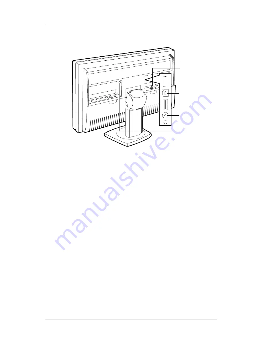
Connect the signal cables:
Figure 13: Signal cable connections
• For
Single View
mode, connect one end of a DVI cable to any
of the DVI inputs of the display (4) or (5). Connect the other
end of the DVI cable to the DVI connector of the graphic board.
• For
DuoView
mode, connect Head1 of the graphic board to
the “left” DVI connector (5) and connect Head2 to the “right”
DVI connector (4).
• Connect the display’s USB upstream connector (6) to a PC USB
downstream connector by means of a USB cable.
• Connect any USB device to one of the display’s USB
downstream connectors (7).
• Connect the DC power input (9) of the display to the supplied
external DC power supply. Connect the other end of the
external DC power supply (10) to a
grounded
power outlet by
means of the proper power cord delivered in the packaging.
4
5
6
7
8
R
L
9
Summary of Contents for LCD Display
Page 1: ...Getting Started Guide Nio Fusion...
Page 2: ...This page intentionally left blank 2 This page intentionally left blank...
Page 7: ...Preface 7 Preface...
Page 20: ...Recommendations for using your display system This page intentionally left blank 20...
Page 21: ...Display controller installation 21 Display controller installation...
Page 30: ...Display Controller Installation This page intentionally left blank 30...
Page 31: ...Display installation 31 Display installation...
Page 42: ...Connecting the signal cables 42 Figure 15 Control panel...
Page 48: ...Cleaning instructions This page intentionally left blank 48...
Page 49: ...Software installation 49 Software installation...
Page 57: ...Where to get more information 57 Where to get more information...
Page 59: ...Where to get more information 59...
Page 60: ...Where to get more information This page intentionally left blank 60...
Page 61: ...Troubleshooting 61 Troubleshooting...
Page 66: ...Configuring Windows This page intentionally left blank 66...
Page 67: ...Technical specifications 67 Technical specifications...
Page 70: ...Technical specifications This page intentionally left blank 70...
Page 71: ...Warranty Statement 71 Warranty Statement...
Page 77: ...Warranty Statement 77...
Page 78: ...Warranty Statement 78...
Page 79: ...Warranty Statement 79...


