background image

5. The On Screen Display (OSD) 

5-4 ___________________________________________________________Barco - LC series - R5976934 - user's manual - Revision 08 - April 2008 

5.2


Activating the OSD 

The OSD can be activated and operated by means of the IR remote control unit (RCU) or the push buttons at the 
right rear side of the monitor. 

RCU 

Icon 

Push button (1: top most) 


Press the 

ADJ

 key to activate the OSD 


Press 

7

 to activate the OSD 

Then the main menu is displayed (default: on the upper left corner of the monitor). 


The OSD will be displayed at the position and size as defined in the OSD setting menu. If no 
modifications have been made via this menu, the OSD will pop up in the upper left corner 
of the monitor in normal mode (not Zoomed In, background opaque) 
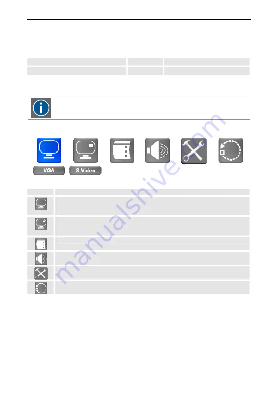


Icon 

description 


signal menu for the first input, 
to select and control the settings of a source 
The currently assigned signal is indicated in the label beneath 


Signal menu for the second input, 
to select and control the settings of a source 
The currently assigned signal is indicated in the label beneath 


OSD setting menu, to control the position, transparency and time out of the OSD 


Audio setting menu, to adjust volume, balance, bass and treble 


Parameter setting menu, to set display address, baud rate, light sensor, lower brightness level, 
ambient light threshold & auto source selection 


Reset menu, to reset to factory defaults. It also shows runtime & serial number of the display 


Summary of Contents for LC series R5976934

Page 1: ...User s manual LC series...

Page 2: ......

Page 3: ...D SDI interface chapter 6 chapter 7 Rev 09 Add SDI HD SDI interface chapter 8 Rev 03 new dimensions LC 47 rev 06 Add SDI HD SDI interface Rev 07 new dimensions LCx 42 LCx47 chapter 9 Revised timing re...

Page 4: ...erlagen die von uns berlassen werden deren Verwertung und Mitteilung ihres Inhaltes an Dritte ist nicht gestattet soweit dies nicht ausdr cklich zugestanden ist Urheber rechte insbesondere auch solche...

Page 5: ...lack of normal maintenance or unauthorized attempts to repair the equipment See also Pre installation requirements and conditions of use BCD system A failure to follow these requirements can result in...

Page 6: ...the software provided by the Seller to the Purchaser in an unmodified form is designed to operate with the hardware identified in the Certificate of Installation and Operation provided i the hardware...

Page 7: ..._______ v Revision sheet To Barco Control Room GmbH Barco Control Room GmbH Barco Control Room GmbH Barco Control Room GmbH An der Rossweid 5 D 76229 Karlsruhe Phone 49 721 6201 0 Fax 49 721 6201 298...

Page 8: ...1 2 1 Unpacking 2 2 2 2 Installation 2 3 2 2 1 Accessories 2 3 2 2 2 Mounting of the table stand optional 2 3 2 2 3 Dimensions of the 42 monitor 2 5 2 2 4 Dimensions of the 47 monitor 2 6 2 3 Examinin...

Page 9: ...3 6 Color 5 26 5 4 OSD setting menu 5 29 5 4 1 Vertical 5 30 5 4 2 Horizontal 5 30 5 4 3 Blend 5 30 5 4 4 Time out 5 31 5 4 5 OSD Zoom 5 31 5 5 Audio setting menu 5 32 5 5 1 Volume 5 33 5 5 2 Balance...

Page 10: ...ngs 7 7 8 Technical data 47 version LCN 47 LCS 47 8 1 8 1 General data 8 1 8 2 LCD panel 8 1 8 3 Electrical data 8 1 8 4 Operating conditions 8 2 8 5 CCFL Cold Cathode Fluorescent Lamp characteristics...

Page 11: ...delivery 12 6 12 3 2 Installation 12 7 12 4 Fixed wall mount 12 8 12 4 1 Scope of delivery 12 8 12 4 2 Installation 12 9 12 4 3 Dimensions 12 10 12 4 4 Wall pattern 12 11 12 5 Tiltable wall mount 12 1...

Page 12: ......

Page 13: ...y analog video and analog and digital RGB data All settings can easily be accessed and modified by means of the Infrared remote control unit and the OnScreenDisplay RS232 remote control is also possib...

Page 14: ...absolutely essential for operation Controlling explains how the monitors are controlled The On Screen Display explains the commands of the menus Maintenance and servicing explains how the equipment ca...

Page 15: ...inted in Courier bold font If you do not heed instructions indicated by this symbol there is a risk of damage to the equipment If you do not heed instructions indicated by this symbol there is a risk...

Page 16: ...he safety and operating instructions should be read before using this unit The operating instructions manual should be retained for future reference All warnings on the device and in the documentation...

Page 17: ...ng a lightning storm or when it is left unattended and unused for long periods of time unplug it from the wall outlet This will prevent damage to the monitor due to lightning and AC power line surges...

Page 18: ...to meet the most stringent safety regulations Exposing flamma ble or combustible materials into close proximity of this device could result in the spontaneous ignition of that material resulting in a...

Page 19: ...zed substitutions may result in degraded performance and reliability fire electric shock or other hazards Unauthor ized substitutions may void warranty Safety check Upon completion of any service or r...

Page 20: ...t is left unattended an unused for long periods of time unplug it from the wall outlet This will prevent damage to the LCD module due to lightning and AC power line surges 1 3 5 Malfunction or Trouble...

Page 21: ...l waste Do not dispose the LCD monitor in waste treated by a waste treatment center The lamp contains mercury inside Please follow the regulations or rules established by local autorithies at its disp...

Page 22: ......

Page 23: ...cking and installation Barco LC series R5976934 user s manual Revision 08 April 2008________________________________________________________________________________________ 2 1 2 Unpacking and install...

Page 24: ...ng clips Remove the banding Take the monitor out Remove the foam For later shipment it is recommended to store the original packaging and to re use it The following components are included in the deli...

Page 25: ...Clearance should be mini mum 15 cm but may be larger depending on the ambient environment Do not install the unit where it may be easily touched or leaned against Avoid locations subject to high vibr...

Page 26: ...Take a screwdriver for recessed head screws size 8 Remove the 4 center screws and washers on the rear side of the monitor Take the table stand and attach its mounting plate to the rear of the monitor...

Page 27: ...series R5976934 user s manual Revision 08 April 2008________________________________________________________________________________________ 2 5 2 2 3 Dimensions of the 42 monitor 2 2 3 1 Front view...

Page 28: ...2 6___________________________________________________________Barco LC series R5976934 user s manual Revision 08 April 2008 2 2 4 Dimensions of the 47 monitor 2 2 4 1 Front view 1139 4 4 684 2 2 4 2...

Page 29: ...he sensors are not blocked by any objects placed in front of the monitor The preset for dim adjustment and bright adjustment can be set and controlled via the OSD cf 5 6 4 L 2 3 2 Side view ENTER Menu...

Page 30: ...Sub 15 pin RGB analog RGB Digital DVI D 24 pin RGB digital HD SDI input Serial Digital BNC SDI HD SDI HD SDI output Serial Digital BNC SDI HD SDI Signal receive transmit RS232 IN D Sub 9 pin RS232 OUT...

Page 31: ...is auto ranging from 100VAC to 240 VAC Connect the video and RGB sources with the respective interface using the included cables 2 5 Switching on and off Use the main power switch on the rear of the s...

Page 32: ...indicated by the arrow and pull upwards the cover top Slide the cover forwards to remove Insert two AA size batteries making sure the polarities match the and marks inside the battery com partment In...

Page 33: ...R5976934 user s manual Revision 08 April 2008________________________________________________________________________________________ 3 1 3 Design and function This chapter introduces the systems and...

Page 34: ...splayed simultaneously either next to each other PAP picture and picture or one source embedded in the other PIP picture in picture The sources can be controlled individually brightness contrast color...

Page 35: ...he LC molecules are completely perpendicular when no voltage is applied and thus they don t change the polarization of light Light simply passes the LC and is blocked by the front end polar izer since...

Page 36: ......

Page 37: ...4 Controlling Barco LC series R5976934 user s manual Revision 08 April 2008________________________________________________________________________________________ 4 1 4 Controlling...

Page 38: ...of the OSD the menu is displayed a menu item is selected and or changed Subsequently the OSD is closed again 4 1 1 The push buttons The push buttons are located on the right rear side of the monitor T...

Page 39: ...______________________________ 4 3 4 1 2 The IR remote control unit The remote control is used for control adaptation and source selection It is also used to switch between standby and operational mod...

Page 40: ...me balance bass and treble of the audio signal 11 Picture controls Except for brightness and contrast these keys have no function for this monitor 12 PHASE Adjust the phase of the signal 13 Freeze Aut...

Page 41: ...mote control the monitors can be controlled individually if they had received a unique display address This address can be displayed by means of the function key F5 on the IR remote control unit Press...

Page 42: ...nce This command has no equivalent in the OSD when e g a signal looks greenish pressing the function key F4 will correct and adjust the color impression F5 Display the monitor address 5 6 1 Set displa...

Page 43: ...On Screen Display OSD Barco LC series R5976934 user s manual Revision 08 April 2008________________________________________________________________________________________ 5 1 5 The On Screen Display...

Page 44: ...main menu is activated by pressing ADJ on the RCU or by pressing push button 7 the bottom most push button the right rear side A selected menu item shows a blue background an unselected menu item a gr...

Page 45: ...The entry will get a button look and a blue dot In case an option is linked to a button use the left and right cursor keys to se lect one of the options In case an option is linked to a button use th...

Page 46: ...been made via this menu the OSD will pop up in the upper left corner of the monitor in normal mode not Zoomed In background opaque Icon description signal menu for the first input to select and contr...

Page 47: ...nu Menus without a submenu will turn blue and display their settings dialog Menus with a sub menu will turn blue and require an additional key stroke to open the settings dialog Use Enter to open the...

Page 48: ...st Press the ADJ key input1 input2 Press 7 Use the left and right cursor keys to navi gate to the signal menu Press 3 and 4 to navigate to the signal menu Press Enter to select Press 2 to select Use t...

Page 49: ...vel adjustment To activate the Display dialog proceed as follows RCU Icon Push button 1 top most Press the ADJ key to activate the OSD Press 7 to activate the OSD Use the left and right cursor keys to...

Page 50: ...Use the up and down cursor keys to navigate to the Brightness Press 5 and 6 to navigate to Brightness Use the left and right cursor keys to in crease decrease the value in steps of 1 The current valu...

Page 51: ...of 1 The current value is indicated The value is applied without any further action 5 3 1 4 Saturation Saturation can be adjusted in the range between 0 and 100 Saturation adjusts the amount of white...

Page 52: ...ween 0 and 100 The black level is the deepest black of the monitor RCU Push button 1 top most Use the up and down cursor keys to navigate to the Black Level Press 5 and 6 to navigate to Black Level Us...

Page 53: ...sh button 1 top most Press the ADJ key to activate the OSD Press 7 to activate the OSD Use the left and right cursor keys to navi gate to the signal menu Press 3 and 4 to navigate to the signal menu P...

Page 54: ...most Use the up and down cursor keys to navigate to the Zoom Press 5 and 6 to navigate to Zoom Use the left and right cursor keys to select one of the options In Out The current value is visualized b...

Page 55: ...display mode 1 1 to the upper left corner of the monitor the allocated position is in the range 600pixel to 1320pixel horizontal counting started on the top left corner and in the range 270pixel to 8...

Page 56: ...ys one source is displayed in full size and the other one is displayed in a small size overlaying the full screen picture The full screen picture is called master source and the other one PIP source B...

Page 57: ...n 1 top most Press the ADJ key to activate the OSD Press 7 to activate the OSD Use the left and right cursor keys to navi gate to the signal menu Press 3 and 4 to navigate to the signal menu Press Ent...

Page 58: ...ush button 1 top most Use the up and down cursor keys to navigate to the PIP Mode Press 5 and 6 to navigate to PIP Mode Use the left and right cursor keys to select one of the options Off Single PAP T...

Page 59: ...and 6 to navigate to Horizontal Use the left and right cursor keys to in crease decrease the value in steps of 1 The current value is indicated increase move right decrease move left Use 3 and 4 to i...

Page 60: ...tings comprise Scaling Noise Reduction Angle Filter Film Mode Detect Sharpness In case of a DVI due to the digital interface no adjustment is required Therefore the dialog only comprises Scal ing Imag...

Page 61: ...r around the content In case Fill is selected the content is displayed on the entire screen which in case the ratio of the source is dif ferent from the ratio of the screen e g a PAL Video 4 3 results...

Page 62: ...gs Use the key FREEZE on the remote control unit to immediately start Auto Adjust During the Auto Adjust process the monitor displays an information Auto Configuration In case Auto Adjust is not selec...

Page 63: ...or keys to in crease decrease the value in steps of 1 The current value is indicated Use 3 and 4 to increase decrease the value in steps of 1 The current value is indicated The value is applied withou...

Page 64: ...5 The On Screen Display OSD 5 22__________________________________________________________Barco LC series R5976934 user s manual Revision 08 April 2008 5 3 5 2 S Video...

Page 65: ...he content would have a black border of 240 pixels both on the left side and on the right side 4 3 if a PAL NTSC source is connected to an input the 4 3 setting displays the source without any distort...

Page 66: ...o select one of the options Off Low Medium High The current selection is visualized by a white caption Use 3 and 4 to select one of the options Off Low Medium High The current selection is visualized...

Page 67: ...o the Film Mode Detect Press 5 and 6 to navigate to Film Mode Detect Use the left and right cursor keys to select one of the options Off On The current selection is visualized by a white caption Use 3...

Page 68: ...alog proceed as follows RCU Icon Push button 1 top most Press the ADJ key to activate the OSD Press 7 to activate the OSD Use the left and right cursor keys to navi gate to the signal menu Press 3 and...

Page 69: ...e current selection is visualized by a white caption Use 3 and 4 to select one of the options 2 2 1 9 2 5 user The current selection is visualized by a white cap tion The selection is applied without...

Page 70: ...User Use the left and right cursor keys to select User Use the down and up cursor keys to select Red Green Blue Use the 5 and 6 to select Red Green Blue Use the left and right cursor keys to in crease...

Page 71: ...lend and time out of the OSD To activate the OSD menu proceed as follows RCU Icon Push button 1 top most Press the ADJ key to activate the OSD Press 7 to activate the OSD Use the cursor keys to naviga...

Page 72: ...monitor 255 right of OSD is level with right of monitor RCU Push button 1 top most Use the up and down cursor keys to navigate to the Horizontal Press 5 and 6 to navigate to Horizontal Use the left a...

Page 73: ...e to the Time out Press 5 and 6 to navigate to Time out Use the left and right cursor keys to in crease decrease the value in steps of 5 The current value is indicated Use 3 and 4 to increase decrease...

Page 74: ...be adjusted as well as bass and treble low frequencies and high frequencies To activate the Audio setting menu proceed as follows RCU Icon Push button 1 top most Press the ADJ key to activate the OSD...

Page 75: ...dominant adjust the setting in negative direction to bring out the left speaker in positive direction to bring out the right speaker RCU Push button 1 top most Use the up and down cursor keys to navig...

Page 76: ...s are predominant adjust the slider to the left In case they are rather faint or missing adjust the slider to the right RCU Push button 1 top most Use the up and down cursor keys to navigate to the Tr...

Page 77: ...or lower brightness level ambient light threshold auto source selection can be done To activate the Display parameter setting menu proceed as follows RCU Icon Push button 1 top most Press the ADJ key...

Page 78: ...the range from 1 to 255 1 is the common address A monitor will listen to the commands explicitly sent to his specific address and to commands sent to the com mon address RCU Push button 1 top most Us...

Page 79: ...parameter defines the brightness the monitor is automatically switched to when the ambient light is below the threshold of the light sensor dark mode requires that the light sensor is set On RCU Push...

Page 80: ...searches for a valid input source signal RCU Push button 1 top most Use the up and down cursor keys to navigate to Auto Source Selection Press 5 and 6 to navigate to Auto Source Selec tion Use the lef...

Page 81: ...tings can be restored It also shows runtime serial number of the display To activate the Reset menu proceed as follows RCU Icon Push button 1 top most Press the ADJ key to activate the OSD Press 7 to...

Page 82: ...adjust range Power switch Off On Off Brightness 80 0 100 Contrast 50 0 100 Color temp User User 3200K 5400K 6500K 9300K Red 255 0 255 Green 255 0 255 Blue 255 0 255 Language English English Auto confi...

Page 83: ...top most Press the ADJ key to activate the OSD Press 7 to activate the OSD Use the left and right cursor keys to navi gate to the signal menu for the first input Press 3 and 4 to navigate to the sign...

Page 84: ...nu Press Enter to select Press 2 to select Use the down cursor keys to open the input signal selection dialog Press 4 to open the input signal selection dialog Use the left and right cursor keys to se...

Page 85: ...sage In case no cable is connected the monitor displays a no cable message In case the timing of the connected source is not compliant to the monitor the monitor displays a invalid mode message For a...

Page 86: ...id signal the monitor switches to standby and dis plays the respective information Whenever one of these messages pop up check the respective item and fix it 5 8 1 Input selection with the function ke...

Page 87: ...1 6 Maintenance and servicing Only authorized personnel should carry out other maintenance work not explicitly mentioned in this manual Never open the case of the monitor without first disconnecting...

Page 88: ...clean it with a soft cloth Stubborn stains may be removed with a cloth lightly dampened with mild detergent solution Never use strong solvents such as thinner or benzene or abrasive cleaners since the...

Page 89: ...i TFT active matrix Pixel number 1920 x R G B x 1080 pixel HDTV Display colors 16 8 millions of colors Viewing angle 176 degree vertical 176 degree horizontal Brightness 500 cd m Contrast ratio 1800 1...

Page 90: ...5 CCFL Cold Cathode Fluorescent Lamp characteristics ambient temperature 25 2 C Characteristic Typ value Lamp voltage 1520 VRMS Lamp current 5 8 mARMS Lamp starting voltage 2370 VRMS 0 C 2160 VRMS 25...

Page 91: ..._________ 7 3 7 6 2 S Video 4 2 3 1 Item specification 1 2 Ground 3 Y 4 C Luminance level 1 0 Vpp Color level 0 286 Vpp Connector type Mini Din 4pin Termination 75 Table 7 7 7 6 3 Component Video mini...

Page 92: ...e blanking level White Yellow Cyan Green Magenta Red Blue Black IRE 100 92 8 78 7 71 5 28 5 21 3 7 2 0 Y mV 700 649 551 501 199 149 51 0 IRE 0 50 11 5 38 5 38 5 11 5 50 0 Pb mV 0 350 80 270 270 80 350...

Page 93: ...YCbCr 100 color bars Values are relative to the blanking level 7 6 4 SDI HDSDI IN OUT BNC LCS 42 only 1 2 1 Signal typ 0 8Vpp 2 Shield SDI HDSDI IN BNC input 75 terminated SDI HDSDI Out BNC output out...

Page 94: ...6 11 Pin signal assignment pin signal assignment 1 Red video input 9 NC 2 Green video input 10 Ground 3 Blue video input 11 NC 4 NC 12 SDA 5 Ground 13 Horizontal sync Composite sync 6 Red video ground...

Page 95: ...5 6 9 Pin signal assignment 1 NC 2 Signal transmit 3 Signal receive 4 NC 5 Ground 6 NC 7 NC 8 NC Table 7 17 7 7 Factory settings Item default adjust range Power switch Off On Off Brightness 80 0 100...

Page 96: ......

Page 97: ...t a Si TFT active matrix Pixel number 1920 x R G B x 1080 pixel HDTV Display colors 16 8 millions of colors Viewing angle 176 degree vertical 176 degree horizontal Brightness 500 cd m Contrast ratio 1...

Page 98: ...8 5 CCFL Cold Cathode Fluorescent Lamp characteristics ambient temperature 25 2 C Characteristic Typ value Lamp voltage 1750 VRMS Lamp current 6 mARMS Lamp starting voltage 2350 VRMS 0 C 2150 VRMS 25...

Page 99: ...n 75 Table 8 7 8 6 3 Component Video 1 2 3 4 5 6 7 8 Item specification Item specification 1 GND 5 GND 2 CB 6 CR 3 GND 7 not connected 4 Y 8 not connected Connector type Mini Din 8pin Termination 75 T...

Page 100: ...lanking level White Yellow Cyan Green Magenta Red Blue Black IRE 75 66 5 52 6 44 0 31 0 22 4 8 6 0 Y mV 525 465 368 308 217 157 60 0 IRE 0 37 5 12 7 24 8 24 8 12 7 37 5 0 Cb mV 0 263 89 174 174 89 263...

Page 101: ...SDI HDSDI Out BNC output output impedance 75 Loop through of the active HDSDI input Table 8 13 8 6 5 DVI 9 16 17 24 1 8 Pin signal assignment pin signal assignment 1 TMDS Data 2 13 NC 2 TMDS Data 2 14...

Page 102: ...6 11 Pin signal assignment pin signal assignment 1 Red video input 9 NC 2 Green video input 10 Ground 3 Blue video input 11 NC 4 NC 12 SDA 5 Ground 13 Horizontal sync Composite sync 6 Red video ground...

Page 103: ...76934 user s manual Revision 08 April 2008________________________________________________________________________________________ 8 7 8 6 8 RS232 OUT 1 5 6 9 Pin signal assignment 1 NC 2 Signal trans...

Page 104: ...manual Revision 08 April 2008 8 7 Factory setting Item default adjust range Power switch Off On Off Brightness 80 0 100 Contrast 50 0 100 Color temp User User 3200K 5400K 6500K 9300K Red 255 0 255 Gr...

Page 105: ...80 160 800 16 625 3 21 600 1 OK OK SVGA 800x600 53 674 85 06 56 250 P P 1048 64 152 800 32 631 3 27 600 1 OK OK 48 363 60 004 65 000 N N 1344 136 160 1024 24 806 6 29 768 3 OK OK 56 476 70 069 75 000...

Page 106: ...1920 88 1125 5 36 1080 4 OK OK 1080p 1920x1080 67 500 60 00 148 500 P P 2200 44 148 1920 88 1125 5 36 1080 4 OK OK 28 13 50 00 74 25 P P 2640 44 148 1920 528 1125 5 38 1080 4 OK OK 33 716 59 94 74 176...

Page 107: ...Samples per active line Active lines per frame scanning format frame rate Hz 1280x720 1650 750 1280 720 1 1 p 60 1280x720 1650 750 1280 720 1 1 p 60 M 1280x720 1980 750 1280 720 1 1 p 50 1920x1080 220...

Page 108: ......

Page 109: ...ries R5976934 user s manual Revision 08 April 2008______________________________________________________________________________________ 10 1 10 Troubleshooting When faults occur which are not describ...

Page 110: ...tween the remote control unit and the IR sensor The picture color is pale or not clear Check the Color setting If you are using YUV terminals make sure that the cables are correctly connected The pict...

Page 111: ...ol Rooms GmbH An der Rossweid 5 D 76229 Karlsruhe Germany Phone 49 721 6201 163 Fax 49 721 6201 298 E mail support de bcd barco com Web www barcocontrolrooms de BARCO N V President Kennedypark 35 B 85...

Page 112: ......

Page 113: ...e radio frequency energy and if not installed and used in accordance with the instruction manual may cause harmful interference to radio communications Operation of this equipment in a residential are...

Page 114: ......

Page 115: ...Required tools Screwdriver for recessed head screws screw size M8 Wall mount and ceiling mount Wrench 10mm 17mm 19mm Allen wrench size 2 5 to adjust the tilt angle of the long short ceiling mount Dri...

Page 116: ...r s manual Revision 08 April 2008 12 2 Table stand The table stand allows adjusting the monitor in height For the 42 version the lower edge can be set between 14mm and 204mm for the 47 versions the lo...

Page 117: ...crews M8x15 These screws are used to attach the table stand Lay the monitor upside down on a clean surface bottom edge flush with e g edge of the table Soil or particles laying on the surface may irre...

Page 118: ...2 4__________________________________________________________Barco LC series R5976934 user s manual Revision 08 April 2008 12 2 3 Dimensions 12 2 3 1 Dimensions of the 42 version 12 2 3 2 Dimension of...

Page 119: ...g the mounting plate up or down respectively For adjusting the table stand in height first uninstall the monitor Never loosen the screws for sliding the plate when the monitor is still attached to the...

Page 120: ...s manual Revision 08 April 2008 12 3 Screen bracket adapter plate The installation of the screen bracket is mandatory for fixation of the wall mount and the ceiling mount 12 3 1 Scope of delivery The...

Page 121: ...ese screws are used to attach the screen bracket To install the screen bracket proceed as follows Lay the monitor upside down on a clean surface Take a screwdriver for recessed head screws screw size...

Page 122: ...mount the screen bracket to the monitor cf Screen bracket adapter plate Use the fixed wall mount to attach the monitor to the wall The drawings show the fixation facility itself and a monitor which i...

Page 123: ...8 for specification of the screws cf Required tools It is the same bracket for 42 and 47 For drilling the holes in the wall it is recommended to use a jig take a sheet of paper A3 and copy the distanc...

Page 124: ...________Barco LC series R5976934 user s manual Revision 08 April 2008 12 4 3 Dimensions The following pictures give an overview about the measurements and dimensions of the 42 version and the 47 12 4...

Page 125: ...008_____________________________________________________________________________________ 12 11 12 4 4 Wall pattern In case of a monitor wall the arrangement of the holes in the wall can be taken from...

Page 126: ...all and allows setting its position in 5 steps between zero and 20 degrees The drawings show the tiltable wall mount at max and min tilt angle 12 5 1 Scope of delivery The tiltable wall mount comes fu...

Page 127: ...ched to the wall by means of 5 screws M8 for specifica tion of the screws cf Required tools It is the same bracket for 42 and 47 For drilling the holes in the wall it is recommended to use a jig take...

Page 128: ..._______Barco LC series R5976934 user s manual Revision 08 April 2008 12 5 3 Dimensions The following pictures give an overview about the measurements and dimensions of the 42 version and the 47 12 5 3...

Page 129: ...first uninstall the monitor Never loosen the screws for setting the tilt angle when the monitor is still attached to the tiltable wall mount Uninstall the monitor Use the included allen wrench 4mm to...

Page 130: ...plate The short ceiling mount fixes the monitor to the ceiling and allows setting the lower screen edge to a distance of the ceiling between 706 5mm and 885 5mm for the 42 versions and between 776mm a...

Page 131: ...3 parts The base plate with the ball point connection to the adjustable bar This base plate will be mounted on the ceiling The adjustable bar The adapter plate to attach to the screen bracket of the m...

Page 132: ...py the distances given in the drawing below Drill 4 holes 10mm to the ceiling in the given distances Attach the ceiling mounting plate Attach the adjustable bar to the ball joint of the ceiling mounti...

Page 133: ...s manual Revision 08 April 2008_____________________________________________________________________________________ 12 19 The knurled bolts of the screen bracket are slid into the keyholes of the wa...

Page 134: ...__________________________Barco LC series R5976934 user s manual Revision 08 April 2008 12 6 3 Dimensions The following pictures give an overview about the measurements and dimensions of the 42 versio...

Page 135: ...__________________________________________________________________________ 12 21 12 6 3 2 Dimension of the 47 version 12 6 4 Tilting Use an allen wrench size 2 5mm To adjust the tilting angle of the m...

Page 136: ...screen bracket to the monitor cf Screen bracket adapter plate The long ceiling mount fixes the monitors to the ceiling and allows setting the lower screen edge to a distance of the ceiling between 123...

Page 137: ...e plate will be mounted on the ceil ing The telescope bar with the ball point connection to adjustable bar The base plate with the ball point connection to the adjustable bar This base plate will be m...

Page 138: ...ceiling in the given distances Attach the ceiling mounting plate Slid in the telescope bar and lock its position by means of a screw M10x60 Secure the screw with a nut and apply the black plastic cap...

Page 139: ...8 April 2008_____________________________________________________________________________________ 12 25 Hook in the knurled bolts of the monitor into the notches and the keyhole of the long ceiling ad...

Page 140: ...__________________________Barco LC series R5976934 user s manual Revision 08 April 2008 12 7 3 Dimensions The following pictures give an overview about the measurements and dimensions of the 42 versio...

Page 141: ...__________________________________________________________________________ 12 27 12 7 3 2 Dimension of the 47 version 12 7 4 Tilting Use an allen wrench size 2 5mm To adjust the tilting angle of the m...

Page 142: ......

Page 143: ...oms GmbH An der Rossweid 5 D 76229 Karlsruhe Germany Phone 49 721 6201 227 Fax 49 721 6201 298 E mail support de bcd barco com Web www barcocontrolrooms de BARCO N V President Kennedypark 35 B 8500 Ko...

Page 144: ...13 Contact 13 2__________________________________________________________Barco LC series R5976934 user s manual Revision 08 April 2008...

Reviews: