


9. General operation example
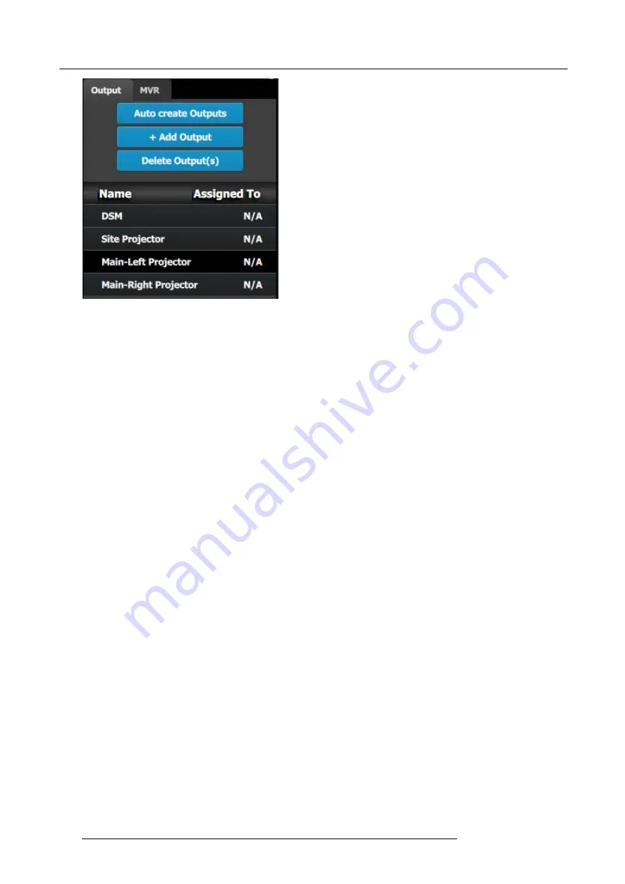
Image 9-8
Note:
The “N/A” at this end refers to the destinations that will be added next.
C5 – Part1: Add Site Screen Destinations
In this section we will create the Site Screen Destination and assign two layers.
1. Click on the
Destination
tab to de
fi
ne destinations for the created outputs.
2. From the diagram area click on the
fi
rst BNC of slot 13 that is the Site Projector output connector. The BNC will be highlighted.
3. Click on the
+Add Screen Destination
blue button to assign the output for the screen destination.
4. When the destination is created a box appears next to the E2 diagram.
5. Double click on the
Destination1
area in the Name list to edit the name.
6. When the area turns blue, click the eraser icon to clear the
fi
eld and type a new name, “Site Screen”.
7. Click on the top at the
Adjust:Site Screen
tab and in the
Assign
menu under the Output section click on the
+Assign Layer to
Destination
blue button to assign a layer to the destination .
8. In the layout area “1 layer” will appear in the green area of the box.
9. Repeat the previous step to add one more layer.
C5 – Part2: Add Main Screen Destinations
In this section we will create the Main Screen Destinations and assign 3 layers.
1. To create the Main Screen destination, please repeat steps 2 thru 6 of the previous stage (C5–Part1) by
fi
rst clicking on the
“Main-Left Projector” BNC.
2. Rename the destination to “Main Screen”.
3. After the destination is created, click on the “Main-Right Projector” BNC and drag it into the “Main Screen” destination box. The
Screen size will immediately change to 3840x1080.
4. Repeat the same steps as above to add layer to the destination but click the add button 3-times to add 3 layers.
C5 – Part3: adjust the projector overlap in Main Screen destinations
In this section we will adjust the projector overlap area for the Main screen.
1. Under the Wide menu in the small diagram area shows the destination, click on the line between the two sites. The line turns
blue.
2. Click on the
Data Double
button and enter “100” for the H overlap value. Note: We will leave the feathering to the default value
of 2.2.
196
R5905948 E2 12/12/2014
Summary of Contents for Event Master E2
Page 1: ...E2 User s guide R5905948 00 12 12 2014...
Page 8: ...Table of contents 4 R5905948 E2 12 12 2014...
Page 16: ...2 Safety 12 R5905948 E2 12 12 2014...
Page 32: ...3 General 28 R5905948 E2 12 12 2014...
Page 82: ...6 GUI orientation Image 6 8 78 R5905948 E2 12 12 2014...
Page 94: ...6 GUI orientation Image 6 20 90 R5905948 E2 12 12 2014...
Page 115: ...6 GUI orientation Image 6 37 Thumbnail view Image 6 38 R5905948 E2 12 12 2014 111...
Page 186: ...7 System Setup 182 R5905948 E2 12 12 2014...
Page 192: ...8 Updating firmware 188 R5905948 E2 12 12 2014...
Page 196: ...9 General operation example Image 9 3 192 R5905948 E2 12 12 2014...
Page 213: ...9 General operation example Image 9 25 R5905948 E2 12 12 2014 209...
Page 216: ...9 General operation example 212 R5905948 E2 12 12 2014...
Page 220: ...10 Maintenance 10 2 Process Overview Flow chart Image 10 2 216 R5905948 E2 12 12 2014...
Page 281: ...10 Maintenance Disregard the heatsink from the spare kit R5905948 E2 12 12 2014 277...
Page 282: ...10 Maintenance 278 R5905948 E2 12 12 2014...
Page 288: ...11 Environmental information 284 R5905948 E2 12 12 2014...
Page 298: ...B Remote Control Protocol 294 R5905948 E2 12 12 2014...
Page 299: ...C Troubleshooting C TROUBLESHOOTING R5905948 E2 12 12 2014 295...
Page 300: ...C Troubleshooting 296 R5905948 E2 12 12 2014...


