background image

SPLIT PACK

REALITY 909

R9040040

INSTALLATION MANUAL

Summary of Contents for BarcoReality 909 Split Pack R9040040

Page 1: ...SPLIT PACK REALITY 909 R9040040 INSTALLATION MANUAL...

Page 2: ......

Page 3: ...BARCO PROJECTION SYSTEMS SPLIT PACK REALITY 909 Art No R5976397 R9040040 Date 09112001 INSTALLATION MANUAL Rev 00...

Page 4: ...Produced by BARCO NV November 2001 All rights reserved Trademarks are the rights of their respective owners BARCO n v Projection Systems Noordlaan5 B 8520Kuurne Belgium Tel 32 56 368211 Fax 32 56 351...

Page 5: ...on guidelines 3 1 Ambient temperature conditions 3 1 Humidity conditions 3 1 Environment 3 1 Environment condition check 3 1 Ambient light 3 1 Which screen type 3 2 Image sizing 3 2 Projector configur...

Page 6: ...rt 3 6 4 Pin configuration D9 connector of the analog input 6 4 Input selection port 3 6 4 Settings on module level 6 4 RGB Analog source with composite sync to port 4 5 6 6 Which signal to port 4 5 6...

Page 7: ...ble of contents 0 3 5976397 SPLIT PACK REALITY 909 09112001 MESSAGES WARNINGS AND FAILURES 8 1 GAMMA CORRECTIONS A 1 Gamma corrections A 1 Gamma warning A 1 Procedure for gamma corrections A 1 INDEX i...

Page 8: ...Table of contents 0 4 5976397 SPLIT PACK REALITY 909 09112001...

Page 9: ...ation fails Installationinstructions Before operating this equipment please read this manual thoroughly and retain it for future reference Installation and preliminary adjustments should be performed...

Page 10: ...e system is equipped with a 3 wire grounding plug a plug having a third grounding pin This plug will only fit into a grounding type power outlet This is a safety feature If you are unable to insert th...

Page 11: ...ventilation is provided 4 Do not block the projector cooling fans or free air movement under and around the projector Loose papers or other objects may not be nearer to the projector than 4 on any si...

Page 12: ...absolute minimum When installing the projector and screen care must be taken to avoid exposure to ambient light directly on the screen Avoid adverse illumination on the screen from direct sunlight or...

Page 13: ...75 lbs Repacking Save the original shipping carton and packing material which will come in handy if you ever have to ship your projector For maximum protection repack your projector as it was original...

Page 14: ...7 58 mm 22 7 inch Power switch Input zone Mains input IR Reciever RS232 561 5 mm 22 1 inch image 2 4 Electronic block back view dimensions 447 5 mm 17 6 inch First position of bend connection Second p...

Page 15: ...nic block top view dimensions 783 07 mm 30 8 inch Corner connector or straight connector is possible Input signals from tube unit Removable safety cable protection Can be used either this side or the...

Page 16: ...650 mm 25 6 inch 244 13 mm 9 6 inch 26 49 mm 1 0 inch 258 5 mm 10 2 inch Iris build in position IR Reciever Fixation plate image 2 10 Electronic block left view dimensions 100 mm 3 9 inch 68 65 mm 2...

Page 17: ...32 mm 20 9 inch 93 5 mm 3 7 inch 7 101 25 mm 4 0 inch 447 5 mm 17 6 inch 90 Angled connection Straight connection in option Connection can be placed on this side or on other side image 2 12 Electronic...

Page 18: ...Packing and dimensions 2 6 5976397 SPLIT PACK REALITY 909 09112001...

Page 19: ...t which has been specifically designed for cleaning optical parts never use industrial strength cleaners on a projectors optics as these will degrade optical coatings and damage sensitive optoelectron...

Page 20: ...g angle In considering the type of screen to choose determine where the viewers will be located and go for the highest gain screen possible A high gain screen will provide a brighter picture but reduc...

Page 21: ...ector configuration Which configuration can be used The projector can be installed to project images in four different configurations image 3 3 rear ceiling rear table front ceiling or front table ima...

Page 22: ...inal lens position Image 3 4 Front Table positioning Projector PD Optical axis projection lens Floor Side view Top view Back view Definitions on the abbreviation on the drawings A Correction value B D...

Page 23: ...view Screen Screen B SH SW SH SW Floor Ceiling Top side facing floor Projector Definitions on the abbreviation on the drawings A Correction value B Distance between ceiling and bottom of the screen C...

Page 24: ...over on the backside by pushing the handle a little towards the bottom of the RCU Image 1 2 Lift up the top side of the cover at the same time image 3 5 3 Insert the batteries as indicated in the RCU...

Page 25: ...ect the cable tube 1 Loosen both indicated screws image 4 1 on the back of the electronic block 2 Remove the protection plate on the back 3 Loosen both indicated screws image 4 1 on the back of the op...

Page 26: ...the back of the optical block image 4 2 Interchanging of the two 36 pin connectors is prevented by a build_in key in the female connectors When these cables need to be unplugged push the tabs on the s...

Page 27: ...ng configuration To change the scanning it is necessary to lift up the protection plate on the top back of the electric block Accesstothescanconnectors 1 Loosen the indicated bolts 3 on each side and...

Page 28: ...Scanconnectorsettings The position of the scan connectors for the different mounting configurations can be summarized as follows After setting the scan connectors put the protection plate back in pla...

Page 29: ...ER to select The identification screen will be displayed menu 4 This screen gives the current information about the projector configuration in the line entitled CONFIG Proj address 001 Soft Version 2...

Page 30: ...Installation setup 4 6 5976397 SPLIT PACK REALITY 909 09112001...

Page 31: ...PORT 4 5 PORT 4 5 PORT 2 PORT 2 PORT 1 PROJECTOR MODE PROJECTOR MODE PORT 1 ON OFF ON OFF POWER MAINS 800 periphals 800 periphals This device complies with part 15 of the FCC rules Operation is subje...

Page 32: ...5 of the FCC rules Operation is subject to following two conditions 1 This device may not cause harmful interference and 2 this device must accept any interference that may cause undesired operation i...

Page 33: ...e desired source or press STBY key The projector displays the selected source or the warm up cycle message When this warm up message appears on the screen handle as described in Start up in Operationa...

Page 34: ...ACPowerconnections 5 4 5976397 SPLIT PACK REALITY 909 09112001...

Page 35: ...peration See installation instructions before connecting to the supply Voir la notice d installation avont de raccorder au r seau See installation instructions before connecting to the supply Voir la...

Page 36: ...g the 75 W switch next to the video input when the projector operates alone or when the projector is the last unit in loop through configuration The switch is set to On signal terminated The switch is...

Page 37: ...p pattern menu will be displayed menu 2 7 Select Selected source 8 Press ENTER to display the Random Access menu menu 3 9 Select Picture Tuning 10 Press ENTER to display the picture tuning menu menu 4...

Page 38: ...a source lower than 32 kHz an optional decoder Limo Pro R9828631 has to be installed Pin configuration D9 connector of the Analog input 1 Not connected 4GREEN 7 Ground RGBS 2 Ground RGBS 5BLUE 8 Hor c...

Page 39: ...on will result in abnormal color balance of the projected image ForcenegativesyncSwitch Switch in the ON position the sync pulses must be negative Switch in the OFF position the sync polarity will be...

Page 40: ...ignal to port 4 5 Component video with tri level sync input can be connected to the projector via port 4 5 The projector detects automatically where the sync signal is located This feature requires a...

Page 41: ...nging the baud rate in chapter Service mode RS 232 OUT RS 232 OUT RS 232 IN RS 232 IN image 2 10 RS232 Connection Computer Port on projector to computer Communication port for communication with perip...

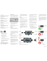
Page 42: ...Sourceconnections 6 8 5976397 SPLIT PACK REALITY 909 09112001...

Page 43: ...ION SERVICE Select with or then ENTER EXIT to return menu1 WARNING RISK OF ELECTRICAL SHOCK NO USER ADJUSTABLE PARTS INSIDE THE FOLLOWING INSTALLATION MENUS ARE RESERVED TO AND TO BE PERFORMED ONLY BY...

Page 44: ...installationadjustmentmode Following flowchart gives the different submenus within the INSTALLATION menu ADJUSTMENT MODE image 7 1 Installation adjustment mode flowchart INSTALLATION PROJECTOR DISTANC...

Page 45: ...ges TheprojectorwillredisplaythePROJECTORDISTANCE1menuwithupdatedvalues for the three parameters 5 Press ENTER to continue with the OPTICAL LENS FOCUSING The same applies to the PD projector distance...

Page 46: ...HEN TIGHTEN THE NUT ENTER TO CONTINUE EXIT TO RETURN Each lens has two focus adjustment points one at the rear of the lens and one at the front To focus the center of the projected image 1 Loosen the...

Page 47: ...ster outside the phosphor area or the CRT CRTphosphorwidth Following phosphor width image 7 4 is used for the green color How to center the raster An info menu is displayed 1 Press the ENTER key to di...

Page 48: ...ttom of the optical block to pivot the BLUE CRT until the center of the blue image and the center of the green image coincide image 7 5 7 When the angle of the blue CRT is corrected tighten the four b...

Page 49: ...ted image These corrections must be repeated for each color The Diagonal image focusing is repeated 3 times first for green then for red and then for blue Attention First be sure that the CRT projecti...

Page 50: ...d color The sheimpflug bolts are located on top of the optical block image 7 7 1 Equalize diagonally the focus from left top to right bottom by turning bolt 04 of the projected color Image 7 7 2 Equal...

Page 51: ...th a pencil or other small object WARNING input not available When using the projector with the RCVDS this warning will be dis played when selecting an input slot of an RCVDS where the input board is...

Page 52: ...com munication error Serial communication error be tween the RCVDS and the projector FAILURE invalid input Input not valid FAILURE PC communica tion error Errorinthecommunicationbetween the projector...

Page 53: ...is pressed a text box with the message ADJUST WITH ARROW KEY will be displayed on the screen menu 3 3 Push the cursor key or to adjust the slope a text box with a bar scale Min to Max will be displaye...

Page 54: ...box with a bar scale 0 16 will be displayed to visualize the magnitude of the correction menu 4 5 Press the ENTER key to return to the GAMMA CORRECTIONS menu To set the parameters back to the factory...

Page 55: ...AL FIRE PROTECTION ASSOCIATION STD 704M SIGNAL TRESHOLD LIMIT VALUE Units TRESHOLD LIMIT VALUE Units BASE METAL ALLOYS METALLIC COATINGS FILLER METAL PLUS COATING OR CORE FLUX OTHERS MATERIAL SAFETY D...

Page 56: ...OR THE RESULTS TO BE OBTAINED FROM THE USE THEREOF VENDOR ASSUMES NO RESPONSABILITY FOR INJURY TO VENDEE OR THIRD PERSONS PROXIMATELY CAUSED BY THE MATERIAL IF REASONABLE SAFETY PROCEDURES ARE NOT ADH...

Page 57: ...ty conditions 3 1 I Image sizing 3 2 Input facilities 6 1 Installation adjustment mode 7 1 Installation guidelines 3 1 L Lens formulas 3 6 M Messages warnings and failures 8 1 INDEX O Operational mode...

Page 58: ...i 2 Index 5976397 SPLIT PACK REALITY 909 09112001...

Reviews: