background image

Using the Operator Settings

62

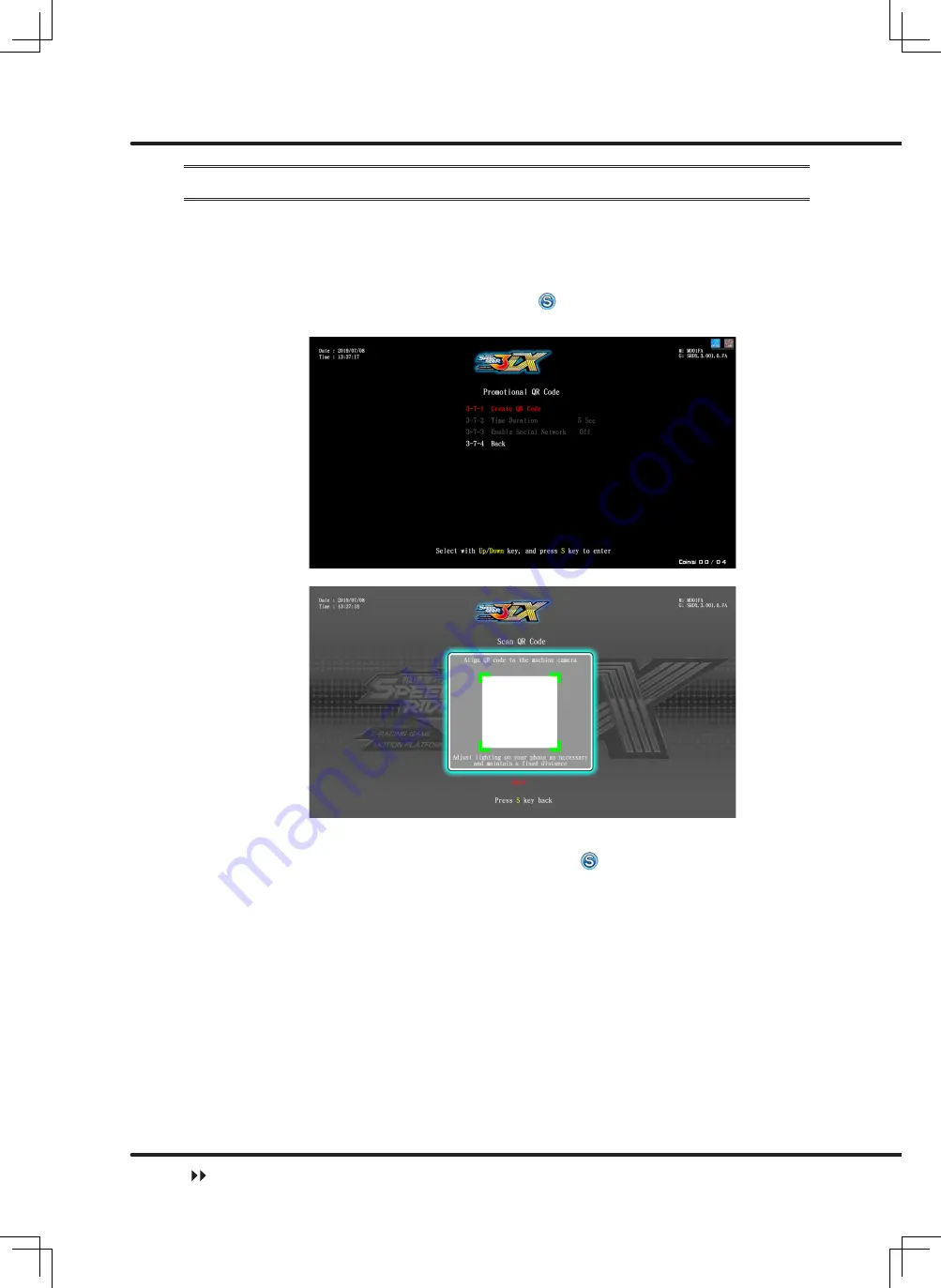
4.5.7 Promotional QR Code

Go to the

 [Promotional QR Code] 

page to insert your store's official website or other 

websites into the game page in the form of a QR code for promotional purposes. The 

set-up steps are as follows:

Enter 

[Operator Settings] > [Game Settings] > [Promotional QR Code]

.

Under the

 [Create QR code]

 option, press to enter the scan QR code page, 

then place the QR code you would like to use under the camera.

If the scan is successful, it will return automatically to the previous page and display 

the successfully scanned QR code. Press the key under the

 [Time duration] 

option, use the 

[Up], [Down]

 keys to adjust the amount of time the promotional QR 

code appears on the standby page, minimum 5 seconds and maximum 20 seconds.

Game Settings

Summary of Contents for IGS Speed rider 3DX

Page 1: ...all instructions in this user manual and pay attention to all descriptions to ensure that the machine is installed correctly Please carefully store this user manual at where it can be easily accessed and read The cabinet and parts of this machine are subject to change for further improvement User s Manual ...

Page 2: ...ical engineering or schooling of the equivalent level and have game machine maintenance management and servicing as their daily work Disclaimer IGS makes no warranty expressed or implied including but not limited to any implied warranties of the correctness and completeness of this document IGS also makes no warranty to any merchantability or fitness for a particular purpose IGS reserves the right...

Page 3: ... fuses and parts other than those designated by IGS To avoid electric shocks or short circuits Before repair or maintenance power must be turned off Do not touch plugs with wet hands Do not immediately unplug or plug in the cabinet When unplugging the electric cord tightly hold the plug and avoid pulling the electric cord WARNING In order to prevent injury to the person who set up use and repair t...

Page 4: ...es around emergency exits fire extinguishers or any other extinguishing equipment The vent located in the bottom of this product is for the cabinet and monitor to emit warm air and do not place any item close to the vent or malfunction might occur A distance of 30 cm or more should be kept between the cabinet and walls another cabinet or the hallway Moving Before moving the cabinet first unplug it...

Page 5: ...4 3 8 Vibration Test 43 4 3 9 Fan Speed Test 44 4 3 10 Drain Valve Test 44 4 3 11 Air Spring Test 45 4 3 12 Electric Jack Test 46 4 4 System Settings 46 4 4 1 Time Settings 47 4 4 2 Connection Settings 48 4 4 3 Country Settings 50 4 4 4 Store Settings 50 4 4 5 Password Settings 51 4 4 6 I O Adjustments 52 4 4 7 Foot Panel Settings 54 4 4 8 Foot Panel Adjustment 54 4 4 9 Air Spring Adjustment 55 4 ...

Page 6: ...alve 87 5 3 10 Maintenance Instructions for the Pedal Sensor 88 5 3 11 Maintenance Instructions for the Light Strips at the Bottom of the Vehicle 89 5 3 12 Maintenance Instructions for the Vehicle Side Light Cover 90 5 3 13 Maintenance Instructions for the tire dec orative hardware light board 91 5 3 14 Maintenance Instructions for the Tire Light Strips 92 5 3 15 Maintenance Instructions for the T...

Page 7: ...he coin box under the standby mode and press the TEST button to enter Operator Settings A Set up the group number and ID of the cabinet Enter Operator Settings System Settings Connection Settings and appoint all cabinets in connection into the same group but provide each cabinet a different ID Example of connecting 2 cabinets viewed from the front of the cabinet Cabinet L Cabinet R Please setup th...

Page 8: ... Settings Enter Operator Settings Game Settings Coin Rate Settings and start to set the number of coins to be inserted for starting and continuing the game C Setting other related items recommended Enter Operator Settings System Settings Time Settings and set the cabinets to be connected to be the same time Enter Operator Settings System Settings to set up the location and name of the store Enter ...

Page 9: ...ameters adjustments Place the vehicle in the center release the brakes and throttle click on the key to reset the motorcycle mid point and reset the throttle press down all the way on the left brake press down all the way on the right brake press down the motorcycle to the maximum point on the left hand side press down the motorcycle to the maximum point on the right hand side then save and exit ...

Page 10: ...re all included If any part is missing or damaged contact your local distributor No Accessories Spec Picture Quantity 1 Power cord 3m 1 5 square meters 2 2 Coin Box Only Power cord 3m 2 5 square meters 1 3 Instruction Manual 1 4 Keys 6008 2 5 Keys 6118 1 6 Connecting cable 2 7 Allen key 2 5MM 1 8 Allen key 3MM 1 9 Vehicle frame 2 List of the accessories ...

Page 11: ...left 1 12 Screen box right 1 13 Machine name panel left light box 1 14 Machine name panel right light box 1 15 Center light box hardware stand 1 16 Camera character acrylic left 1 17 Camera character acrylic right 1 18 Connector stand scanner description PVC foam board 1 An overview of the cabinet ...

Page 12: ... decorative PVC foam board right 1 21 Upper decorative PVC foam board center 1 22 Cabinet connection bracket A 4 23 Cabinet connection bracket Cover A 2 24 Cabinet connection bracket Two 1 25 Cabinet connection bracket Three 1 26 Card description support bracket 2 27 PVC board fixing frame 7 28 Maintenance door strike plate 4 29 U shaped hook 4 ...

Page 13: ...Introduction of the Cabinet 12 1 2 An overview of the cabinet Viewed from the front and side 2177 mm Name of the parts ...

Page 14: ...Introduction of the Cabinet 13 2706 mm 2188 mm Name of the parts ...

Page 15: ...f the exterior cabinet DX Light box Cardboard Right SR3 Light box Acrylic board Vehicle body 42 LCD 4 Speaker Connector stand PVC board 8 Speaker Pedal sensor Central connector stand Cardboard Left Vent Left and right side guide light acrylic Name of the parts ...

Page 16: ...r Air compressor inlet Maintenance Door up Motherboard POWER Fan Light box maintenance door I O board Maintenance Door down AMP Power Inlet Adjustment caster Machine light box maintenance door in front of PVC board HUB Vibration amplifier POWER transformer Name of the parts ...

Page 17: ...eak left Arrow Keys Pedal sensor left Sensor Tire light Tail light Tire frame ligh Platform guide light upper Platform guide light lower Solenoid valve placement area Break right Handle Pedal sensor right S Boost Vehicle side light Vehicle bottom decorative light Specification of the cabinet ...

Page 18: ...17 Name of the interior parts Coin funnel Coin Box Control panel Coin acceptor Air compressor Airbag regulator Drain control Water collection tray Counter Test Volume Service Control panel Transporting or moving the cabinet ...

Page 19: ...B light bar Screen frame backlight controllable RGB light bar Instructions guide light controllable RGB light bar Left and right guide lights controllable RGB light bar Bass top and bottom guide lights controllable RGB light bar Rear brake light LED light panel Tire rim lights LED light panel Tire lights controllable RGB light bar upper Platform edge lights controllable RGB light bar lower Platfor...

Page 20: ...ve the plug so as to prevent Before moving the cabinet unplug the electric cord to avoid accidents When moving this product be aware of the obstacles and the surface of the ground to avoid accidents and damages to the cabinet When moving this product at least two personnel should work together so asto avoid accidents or injuries Reminders for installation This product should be placed indoors Do n...

Page 21: ...the screws Do not dismount replace or convert the product without our permission in order to avoid damage and human injury due to improper operation Check and maintain the machine regulary Keep Warning stickers clean and legible Replace it immediately when the word are not legible or the dirt can t be removed Please contact our service center when performing any work that is not described in this ...

Page 22: ...ve the 1 and 2P cabinets up against the central connector stand and then secure with screws from the inner side 3 Install the machine name light box on the cabinet according to the diagram 4 Secure the DX light box on the machine light box cabinet 5 Secure the SR3 light box on the machine light box cabinet Machine assembly ...

Page 23: ... 7 After positioning the vehicle body platform and the screen cabinet secure with screws according to the diagram 8 Open the maintenance door and then secure U shaped hook with screws from the inner side 9 Install the central decorative PVC board on the connector stand Machine assembly ...

Page 24: ...me power connection 2 5 Connection and Power Basic settings Open the coin box under the standby mode and press the TEST button to enter Operator Settings A Set up the group number and ID of the cabinet Enter Operator Settings System Settings Connection Settings and appoint all cabinets in connection into the same group but provide each cabinet a different ID Example of connecting 2 cabinets viewed...

Page 25: ... the connection here Please setup the connection here Cabinet L Cabinet R Please setup the connection here Please setup the connection here B Coin Rate Settings Enter Operator Settings Game Settings Coin Rate Settings and start to set the number of coins to be inserted for starting and continuing the game Connection and Power ...

Page 26: ...ferent ID If four cabinets are connected then appoint their ID as 1P 2P 3P and 4P 1 Under the standby mode open the coin box and press the TEST button to enter Operator Settings 2 Enter System Settings Connection Settings 3 Assign the cabinets into the same group but different ID Example of connecting 2 cabinets viewed from the front of the cabinet Cabinet L Cabinet R Please setup the connection h...

Page 27: ...Please setup the connection here Checking connection setup 4 After completing all settings the screen should display cabinets to be connected 5 For further connection testing open the coin box and press the TEST button to enter Operator Settings then enter Hardware Test Connection Test to test whether the connection is normal or not For detailed instructions refer to 4 3 5 Connection Test Setting ...

Page 28: ...rs can be more immersed in the thrill and excitement of the racing scenario 3 2 Distinctive plays Two Game Modes Single player challenge the single player best time record ranking Multiplayer linking up to four player can be linked to challenge each other Intuitive game controls including motion cabinet left and right leaning and tilting Infrared sensory system simulated tilting realistic wind pre...

Page 29: ...ons of the game 28 3 3 Game control Instructions of the control buttons In scene selection press Left or Right to select the scene use Up or Down to proceed in clockwise or anti clockwise direction Game control ...

Page 30: ...f the game 29 To instantly throttle players can imitate the way to raise the front wheel of real motorcycles Press the button for the BOOST Leaning the motorcycle to the left and right end can make turns Game control ...

Page 31: ...n decrease wind resistance and increase the acceleration speed When turning press Left Brake can do drifting For curves press Right Brake to decelerate When the game is in process press Up Down Right Brake at the same time to stop the game Game control ...

Page 32: ...t to select the text then press the key to confirm After scanning the QR code at the bottom right corner to share your results press Up on the standby page another token is required and scan the QR code again to receive the mystery prize Game control ...

Page 33: ...hicle selection page and the prize will be displayed automatically 3 4 Instruction of the game display Distance to destination Time Number of nitrogen Speed RPM gauge Player avatar Rank Distance to destination Instruction of the game display ...

Page 34: ...ings Password Settings I O Adjustments Foot Panel Settings Foot Panel Adjustment Air Spring Adjustment Fan Mode Settings Electric Jack Settings Game Settings Coin Rate Settings Sound Settings Difficulty Settings Number Of Laps Multiplayer Settings Flow Time Settings Promotional QR Code Motion Default Settings Error Message Clothes Setting Income Data Daily Income Monthly Income Total Income System...

Page 35: ...80 0 10 20 30 40 50 60 70 80 90 100 Sound Settings Daytime Volume Setting Standby Volume 80 0 10 20 30 40 50 60 70 80 90 100 Sound Settings Daytime Volume Setting Menu Volume 70 0 10 20 30 40 50 60 70 80 90 100 Sound Settings Daytime Volume Setting Music Volume 100 0 10 20 30 40 50 60 70 80 90 100 Sound Settings Daytime Volume Setting Scene Volume 70 0 10 20 30 40 50 60 70 80 90 100 Sound Settings...

Page 36: ...ff On Off Multiplayer Settings Max Bonus Game 02 1 10 Unlimited Multiplayer Settings Challenge in game player On On Off Flow Time Setting Select Photo Frame 10 Sec 5 Sec 10 Sec 15 Sec 20 Sec 25 Sec 30 Sec 35 Sec 40 Sec 45 Sec 50 Sec 55 Sec 60 Sec Flow Time Setting Authorize Photo 5 Sec 5 Sec 10 Sec 15 Sec 20 Sec 25 Sec 30 Sec 35 Sec 40 Sec 45 Sec 50 Sec 55 Sec 60 Sec Flow Time Setting Select Mode ...

Page 37: ...ode Comfortable Mode Exciting Mode Error Message On On Off Clothes setting Short sleeve Short sleeve Long sleeve 4 2 Using the Operator Settings To enter the Operator settings make sure the cabinet is on the standby mode Notes When the game is in process press Up Down Right Brake at the same time to stop the game Open the door of coin box and press the TEST button to enter Operator Settings as sho...

Page 38: ...t to test if all software is normally functioning or not 1 Enter Operator Settings Hardware Test and the screen will display as follows 2 To enter the sub menu use the Up and Down buttons to move the cursor and then press the button to confirm 3 Regarding the detailed descriptions of testing all hardware in the sub menu refer to the following instructions Hardware Test ...

Page 39: ...in red but poorly sensed ones will remain in white Test Press the corresponding button Service S BOOST Up Press the corresponding direction button Well sensed devices will display in red but poorly sensed ones will remain in white Down Left Right Sensor Lean or place your hand on top of the sensor Throttle Turn the throttle Neutral position is 0 000 Full throttle is around 1 000 Left brake Right b...

Page 40: ...her white balance color level and lattice are normally functioning or not 1 Enter Operator Settings Hardware Test Screen Test 2 After you enter the page of Screen Test the system will soon complete the testing and the screen will display the following picture for you to adjust white balance color level and lattice 3 Press the button again and the screen will display red green blue white and black ...

Page 41: ...wn keys to select Back then press again to return to previous menu 4 3 4 Lamp Test In the page of Lamp Test you can test whether the lights are functioning well or not 1 Enter Operator Settings Hardware Test Lamp Test 2 Choose Auto Test and press button then the system will test all lights in sequence During testing lights will blink as follows 3 If you want to test a certain light Use the Up Down...

Page 42: ... Test After you have assigned a group number for the cabinets to be connected and set up the ID you can enter the page of Connection Test to test whether each cabinet of the same group is normally connected 1 Enter Operator Settings Hardware Test Connection Test 2 In the page of Connection Test press the button and the system will start Hardware Test ...

Page 43: ...ion failure for 3P and 4P then you can simply ignore this message When the connection could not be built 1 Check if internet wires are correctly plugged in 2 Regarding cabinets to be connected enter Operator Settings System Setting Connection Setting and check if all cabinets are appointed to the same group but a different ID 4 3 6 Camera Test In the page of Camera Test you can test whether the Ca...

Page 44: ...s 3 Open coin box door to check counter for any issues 4 After completing the test use Up Down keys to select Back then press again to return to previous menu 4 3 8 Vibration Test In the page of Vibration Test you can test whether the Vibration is normally functioning or not 1 Enter Operator Settings Hardware Test Vibration Test 2 After selecting Vibration Test and pressing the key the system will...

Page 45: ...el the test 3 On this page Variable can also be switched On Off 4 After completing the test use Up Down keys to select Back then press again to return to previous menu 4 3 10 Drain Valve Test On the Drain Valve Test page you can test if the drain valve is functioning properly The testing steps are as follows 1 Enter Main Menu Hardware Test Drain Valve Test 2 Press the button to start the test 3 Af...

Page 46: ...re Test Air Spring Test 2 To do the Auto Test After pressing the Auto Test button the system will test the height of each air spring in sequence 3 Move the cursor up and down select the position to be tested and press the button to start the test 4 After the test is complete use the Up and Down keys to select Return to Previous Page press the button to return to the previous menu Hardware Test ...

Page 47: ...tton to return to the previous menu 4 4 System Settings In the page of System Settings you can set up system time connection Country Settings Store Settings Password Setting or I O Adjustments 1 Enter Operator Settings System Settings and the screen will display as follows 2 To enter the sub menu use Up Down select item and press the button to confirm 3 For detailed descriptions for each sub menu ...

Page 48: ... the setting steps are as follows Use the Up and Down keys to select the item to be adjusted press the button press the Up and Down keys to adjust and then press the button to confirm After the time adjustment is confirmed use the Up and Down keys to select Return to Previous Page After the button is pressed the option to reboot will appear This setting will only take effect after restarting If yo...

Page 49: ...you have four cabinets to connect you can appoint their ID as 1P 2P 3P and 4P Examples of connecting four cabinets Cabinet 1P Cabinet 2P Please setup the connection here Please setup the connection here Cabinet 3P Cabinet 4P Please setup the connection here Please setup the connection here Setup steps are as follows 1 Enter Operator Settings System Settings Connection Settings 2 Appointing the gro...

Page 50: ...ess the button to confirm 4 You can use the Up Down keys to select Network Information press to enter the page then check MAC Address IP Address Subnet Mask Gateway are all correct 5 After the adjustment has been confirmed use the Up Down keys to select Back press the key to return to the previous menu System Settings ...

Page 51: ...e previous menu 4 4 4 Store Settings In the option of Store Settings you can set up the name of your store which will be displayed in players information of the ranking list 1 Enter Operator Settings System Settings Store Settings 2 When the cursor is pointing to Store Settings press the button and the screen will display a page for you to key in the name of your store 3 Use the Up Down keys selec...

Page 52: ...lows 1 Enter Operator Settings System Settings Password Settings 2 Go to the page and enter the original password first before entering the new password 3 In the option Enter original password press the key use the Up Down keys to adjust the digits press the key to confirm and move on to the next digit 4 After the original password has been confirmed press to Enter new password and Confirm new pas...

Page 53: ...the Up Down keys to select Back and press to return to the previous menu 4 4 6 I O Adjustments In the page of I O Adjustments you can adjust each operating function of the motorcycle 1 Enter Operator Settings System Settings I O Adjustments 2 Enter the page of I O Adjustments and make sure the cursor is pointing to Start Adjustments then press button to manual adjustment System Settings ...

Page 54: ...dle position releasing the brake and throttle Then press button 4 Under the Full Throttle option fill up the throttle and press the key to move on to the next reset option Each option will have a corresponding image 5 Once all of the options have been adjust press the key to save and return to the previous menu System Settings ...

Page 55: ...tton 3 After the setting is complete use the Up and Down keys to select Return to Previous Page press the button to return to the previous menu CAUTION Adjusting the Foot Panel Settings will affect the safety of the game please use with caution 4 4 8 Foot Panel Adjustment On the Foot Panel Adjustment page you can adjust the pressure sensing settings The adjustment steps are as follows 1 Go to Main...

Page 56: ...t On the Air Spring Adjustment page you can adjust the Air Spring of the motorbike The adjustment steps are as follows 1 Go to Main Menu System Settings Air Spring Adjustment 2 After entering the page select and press the Begin Adjustment button to begin the adjustment 3 After the adjustment is complete use the Up and Down keys to select Return to Previous Page press the button to return to the pr...

Page 57: ...he button to return to the previous menu 4 4 11 Electric Jack Settings On the Electric Jack Settings page you can adjust the settings of the Electric Jack switch The setting steps are as follows 1 Go to Main Menu System Settings Electric Jack Settings 2 Use the Up and Down keys to select On or Off confirm and press the button 3 After the setting is complete use the Up and Down keys to select Retur...

Page 58: ...ings Game Settings and the screen will display as below 2 To enter the sub menu use Up Down select item and press the button to confirm 3 For detailed descriptions for each sub menu refer to the following sections After the adjustment has been confirmed use the Up Down keys to select Back press the key to return to the previous menu Game Settings ...

Page 59: ...se Up Down keys to select Back then press again to return to previous menu 4 5 2 Sound Settings In the page of Sound Settings you can set volumes for day time volume and night time volume 1 Enter Operator Settings Game Settings Sound Settings 2 Choose day time volume or night time volume to be set up by using the Up and Down buttons and press the button 3 Day time volume and Night time volume init...

Page 60: ...ious menu 4 5 3 Difficulty Settings In the Difficulty Settings you can set up the level of the game The default setting is Normal The set up steps are as follows 1 Enter Operator Settings Game Settings Difficulty Settings 2 Choose Easy Normal Hard by using the Up and Down buttons and press the button to return to the previous menu Game Settings ...

Page 61: ... select Back press the key to return to the previous menu 4 5 5 Multiplayer Settings On the page of Multiplayer Settings you can switch the champion win streak free play On Off and also decide whether to turn on the challenge in game player setting The set up steps are as follows 1 Operator Settings Game Settings Multiplayer Settings 2 In the Free play for champion option press the key use the Up ...

Page 62: ... select Back press the key to return to the previous menu 4 5 6 Flow Time Settings On the page of Flow Time Settings you can determine the duration of each process 1 Enter Operator Settings Game Settings Flow Time Settings 2 Use the Up Down keys to select the item you would like to adjust press the S key use the Up Down keys to adjust then press the key to confirm 3 After the adjustment has been c...

Page 63: ...ettings Promotional QR Code 2 Under the Create QR code option press to enter the scan QR code page then place the QR code you would like to use under the camera 3 If the scan is successful it will return automatically to the previous page and display the successfully scanned QR code Press the key under the Time duration option use the Up Down keys to adjust the amount of time the promotional QR co...

Page 64: ...e the Up Down keys to adjust On Off then press the key again to confirm 5 After the adjustment has been confirmed use the Up Down keys to select Back press the key to return to the previous menu 6 The QR code you would like to use for promotion will appear during the standby mode and the store name will also appear at the top Game Settings ...

Page 65: ...efault Settings 2 Use the Up and Down keys to select Comfort Mode or Power Mode press the button to return to the previous menu 4 5 9 Error Message On the Error Message page you can adjust whether the error message is displayed The setting steps are as follows 1 Go to Main Menu Game Settings Error Message 2 Use the Up and Down keys to select On or Off press the button to return to the previous men...

Page 66: ...d Down keys to select Return to Previous Page press the button to return to the previous menu 4 6 Income Data On the page of Income Data you can view income information 1 Enter Operator Settings Income Data and the screen will display as below 2 To enter the sub menu move the cursor by using Up and Down buttons and press the button to confirm 3 For detailed descriptions for each sub menu refer to ...

Page 67: ...hat day Continue Number of times coins were inserted to continue games that day Freeplay Total number of freeplays on that day Bonus Total number of winner bonus games on that day Versus Total number of online games on that day Number of times service button was pressed Number of service buttons used that day Current coin s Actual number of coins deducted that day Current Service Number of service...

Page 68: ...tart new games that month Continue Number of times coins were inserted to continue games that month Freeplay Total number of freeplays in that month Bonus Total number of winner bonus games in that month Versus Total number of online games in that month Number of times service button was pressed Number of service buttons used that month Current coin s Actual number of coins deducted that month Cur...

Page 69: ...w games in total Continue Number of times coins were inserted to continue games in total Freeplay Total number of freeplays overall Bonus Total number of winner bonus games overall Versus Total number of online games overall Number of times service button was pressed Number of service buttons used overall Current coin s Actual number of coins deducted overall Current Service Number of service butt...

Page 70: ...t has been confirmed use the Up Down keys to select Back press the key to return to the previous menu 4 7 1 Income Data Reset On the page of Income Data Reset you can delete all of the data The set up steps are as follows 1 Operator Settings System Reset Income Data Reset 2 Press the key at the option Enter password use the Up Down keys to set the password digits you would like to use press the ke...

Page 71: ...appear in red 4 If you select No you will return to the previous menu directly 5 If the password is entered incorrectly the words Incorrect password will appear in red below 6 If no adjustments are to be made use the Up Down keys to select Back and press the key to return to the previous menu System Reset ...

Page 72: ...gs 2 Press the key at the option Enter password use the Up Down keys to set the password digit you would like to use and press the key to confirm and move to the next digit After the four digits have been entered Yes or No for the Reset query will appear use the Up or Down button to select then press the key to confirm 3 If you select Yes if Reset was successful the words Reset Complete will appea...

Page 73: ...eys to select Back and press the key to return to the previous menu 4 7 3 Ranking Board Reset On the page of Ranking Board Reset you can reset all data on the ranking list 1 Enter Operator Settings System Reset Ranking Board Reset 2 Enter the page and the query for Reset Yes or No will appear directly use the Up or Down button to select then press the key to confirm 3 If you select Yes the words R...

Page 74: ... 7 4 Reset Player Photo On the Reset Player Photo page you can restore the avatar photo to the default setting The set up steps are as follows 1 Enter Operator Settings System Settings Reset Player Photo 2 Enter the page and the query for Delete Yes or No will appear directly use the Up or Down button to select then press the key to confirm 3 If you select Yes the words Reset Complete will appear ...

Page 75: ... press the key to return to the previous menu 4 7 5 Update Progress On the Update progress page you can check it there is an update for the latest version The set up steps are as follows 1 Enter Operator Settings System Settings Update Progress 2 Enter the page to check if you have the latest version press the key to confirm and return to the previous menu System Reset ...

Page 76: ...ducing sound Check if LED lights and buttons are normal Check if the display of the screen is clear enough Check if the throttle and brake are normal Check if the function of leaning the motorcycle to the left and right is normal 5 2 Cleaning and Maintenance Screen To clean the LCD screen make sure to use a soft dry cloth without showing the end of the thread and cloth made of microfiber is recomm...

Page 77: ... Replacing Parts 5 3 1 Maintenance Instructions for the Upper Light Box Light Strips Remove the decorative acrylic fixing screws decorative acrylic After unscrewing the screws of the acrylic remove the light strips for maintenance Light Box Cover ...

Page 78: ...e the light strip securing screws a n d p e r f o r m t h e maintenance light strip Remove the fixing screws from the light box maintenance door light box maintenance door Remove the light strip securing screws a n d p e r f o r m t h e maintenance ...

Page 79: ...nce Instructions for the Camera Remove the fixing screws from the light box maintenance door light box maintenance door Remove the camera back cover hardware camera back cover hardware After removing the securing screws of the camera perform the replacement ...

Page 80: ...s 79 5 3 3 Maintenance Instructions for the Screen Lower Light Strips Remove the screen s decorative acrylic fixing screws screen s decorative acrylic Remove the light s t r i p s a n d t h e n begin the light strip maintenance light strip ...

Page 81: ...0 5 3 4 Maintenance Instructions for the Screen Open the Rear Maintenance Door with the corresponding key and detach the screen cables Rear Maintenance Door Remove the screen frame fixing screws Remove the screen frame back cover fixing screws ...

Page 82: ... and repair Replacing parts 81 Remove the screen frame fixing screws and carefully remove the screen frame back cover Screen Frame Back Cover After replacing the screen reinstall the screen by reversing the steps ...

Page 83: ...intenance Instructions for the Air Vent Blowers Remove the air vent acrylic fixing screws air vent acrylic Remove the blower fixing frame Remove and replace the blowers according to the diagram once completed reinstall b y r e v e r s i n g t h e steps ...

Page 84: ...3 5 3 6 Maintenance Instructions for the Subwoofer Light Board Remove the subwoofer fixing screws and carefully remove the subwoofer mesh subwoofer mesh Remove the light board fixing screws according to the diagram and then begin maintenance ...

Page 85: ... Guide Light Boards Remove the subwoofer fixing screws and carefully remove the subwoofer mesh subwoofer mesh Remove the fixing hardware of the left and right side guide lights according to the diagram Remove the light board fixing screws according to the diagram and then begin maintenance light board ...

Page 86: ...the Maintenance Door with the corresponding key Maintenance Door De pressurize the internal pressure of the air compressor e n s u r e t h a t t h e pressure value is 0 then remove the pressure regulating valve connection piping then remove t h e p r e s s u r e regulating valve unit s securing screws ...

Page 87: ...d repair Replacing parts 86 Remove the air compressor tray s securing screws Pull forward the tray h a n d l e f r o m t h e front and pull the air compressor out of the cabinet to perform the maintenance tray handle ...

Page 88: ... Airbag Solenoid Valve Remove the platform maintenance upper cover fixing screws and carefully remove the upper cover upper cover A f t e r r e m o v i n g t h e s c r e w s t h a t lock the solenoid valve in place the solenoid valve may be taken down for maintenance solenoid valve ...

Page 89: ...e Pedal Sensor Remove the pedal sensor upper cover securing screws pedal sensor upper cover Remove the pedal s e n s o r m o d u l e securing screws pedal sensor module After removing the acrylic fixing screws r e m o v e t h e l i g h t strips according to the diagram light strips ...

Page 90: ...Maintenance Instructions for the Light Strips at the Bottom of the Vehicle Remove the light box frame fixing screws and carefully take down from the side light box frame Remove the light strip fixing brackets and then begin the light strip maintenance ...

Page 91: ... Side Light Cover Remove the securing screws of the vehicle side plastic cover vehicle side plastic cover Remove the side light cover fixing screws Remove the securing screws on top of the light cover After replacing the light strips reinstall b y r e v e r s i n g t h e steps light strips ...

Page 92: ... repair Replacing parts 91 5 3 13 Maintenance Instructions for the tire decorative hardware light board R e m o v e t h e t i r e decorative hardware and acrylic R e m o v e t h e t i r e decorative plastic components ...

Page 93: ... securing screws once completed reinstall by reversing the steps 5 3 14 Maintenance Instructions for the Tire Light Strips Remove the fixing screws of the tire plastic components a c c o r d i n g t o t h e diagram and then begin maintenance tire plastic components ...

Page 94: ...or the Tail Light Board Remove the fixing screws of the tire plastic components a c c o r d i n g t o t h e diagram and then begin maintenance tire plastic components 5 3 16 Maintenance Instructions for the Vehicle Body IO Board Remove the securing screws of the fuel tank cap ...

Page 95: ...uel tank cap from the top and perform the IO board maintenance 5 3 17 Maintenance Instructions for the Throttle Brake Sensor Remove the securing screws of the fuel tank cap Remove the sensor fixing screws according to the diagram and then begin maintenance ...

Page 96: ...ts 95 5 3 18 Maintenance Instructions for the Vehicle Movement Sensor Remove the securing screws of the vehicle left side plastic outer cover plastic outer cover After replacing the vehicle movement sensor reinstall by reversing the steps ...

Page 97: ... the plugs between speakers and power amplifier are coming off If this problem persists contact your local distributor to replace parts The light of the button on the oil tank is not on Enter Operator Settings Hardware Test Lamp Test and run the testing of wrongly functioning lights If lights do not respond follow the instruction of 5 3 12 Replacing the button light of the oil tank to disassemble ...

Page 98: ...nd check if the maximum volume is adjusted to its minimum value Open the maintenance door of the cabinet and check if the volume of the power amplifier is adjusted to its minimum value Check if the power of power amplifier is turned on Check if the audio cable connected the power amplifier and cabinet is coming off If this problem persists contact your local distributor Air Spring not moving Check...

Page 99: ...Appendix 1 warning labels of the cabinet warning labels of the cabinet 98 ...

Page 100: ...ES SYSTEM CO LTD http www igs com tw Distributor BAOHUI ELECTRONIC SCIENCE TECHNOLOGY CO LTD Add Room C1 C3 C5 Star Carton City No 143 East Yingxing Rd Donghuan Street Panyu District Guangzhou China Tel 86 20 23885180 23885868 Fax 86 20 23885190 Http www baohuigame net Email baohui789 126 com EN 20200519 D3 ...

Reviews: