background image

Bante904P Portable Conductivity/DO Meter 

21 


Communication 

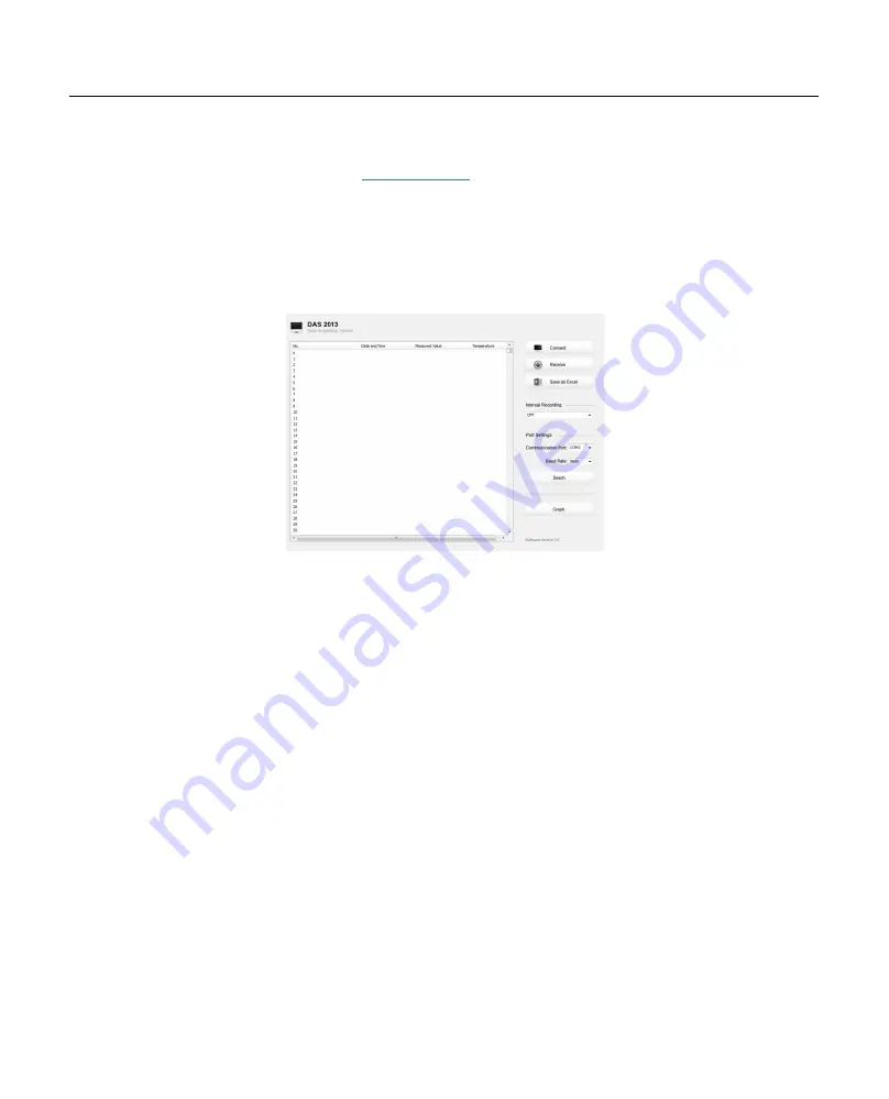
Bante Instruments provides a Data Acquisition System that can be used to transfer data, receive the measuring values or import the data to Excel. You are 
able to download this software from our official website at 

www.bante-china.com

Before installation, ensure that Windows 7/8/10 operating system has 

been installed on your computer. 
 

Receiving data 


Connect the USB cable to meter and computer. Click the DAS icon, the system will automatically scan an available communication port and show the 


message box “Found a port on your computer”. 


Click the 

OK

 button, the application starts. 


Click the 

Connect


button, the screen shows “Port is connected” indicate that 

the communication between the meter and the computer has been 


established.   


Click the 

OK

 button to confirm. 


Click the 

Receive

 button, the stored data automatically transfer to computer. 


Interval recording 

This function is used for recording the measuring value within the specify time period. 


Click the 

Interval Recording

 button and select a time option. 


Click the 

Receive

 button, the measured value will automatically send to data sheet. 


The first data need 1 minute to be shown on screen. 


Do not press any key on meter during the Interval Recording mode, it will cause communication interruption. 


Graph mode 

This function is used for viewing the variations of the measured parameter continuously.   
Click the 

Graph

 button, the screen immediately shows the curve graph. To quit current mode, click the 

Back

 button. 


Create the excel file 

When the transfer is completed, click the 

Save as Excel

 button, the measured values in the data sheet will automatically convert to Excel file.   


Once the software is closed, all received data will be lost and can not be recovered. 


Summary of Contents for 904P

Page 1: ...Bante904P Portable Conductivity DO Meter Instruction Manual BANTE INSTRUMENTS CO LTD...

Page 2: ...conditions Relative humidity is less than 80 Ambient temperature is greater than 0 C and less than 60 C No potential electromagnetic interference The following list describes the standard components...

Page 3: ...rement mode Stable icon Indicates the measuring value has stabilized Calibration mode icon Indicates the meter is in the calibration mode Hold icon Indicates the measuring value has been locked Setup...

Page 4: ...ress and hold the key for 3 seconds Stores current reading to memory Increase value or scroll up through the menu item Views the calibration report or data logs Decrease value or scroll down through t...

Page 5: ...e meter allows using the DC5V power adapter with USB cable for power supply NOTE take out the batteries Connecting the Sensors Take out the electrode from the carrying case Conductivity Electrode or D...

Page 6: ...be excess electrolyte solution will drain out 4 Be sure the cathode of probe makes contact with membrane cap the electrolyte solution in membrane cap should be without an air bubble Prior to Use Remov...

Page 7: ...MENU DESCRIPTION OPTIONS DESCRIPTION DEFAULT Cell Constant Set the cell constant to match connected electrode K 0 1 K 1 K 1 K 10 User Defined Temperature Coefficient Set the linear temperature compens...

Page 8: ...mg L mmHg Degrees Fahrenheit mg L Milligrams per liter ppm Parts per million mmHg Pressure unit kPa Pressure unit GENERAL OPTIONS MENU DESCRIPTION OPTIONS DESCRIPTION DEFAULT Stability Criteria When...

Page 9: ...er the setup menu and the or key to select the menu item e g CELL P 01 1 2 Press the Enter key the display shows an option 1 3 Press the or key to select the desired option 1 4 Press the Enter key to...

Page 10: ...splay the meter is now switched to the automatic temperature compensation mode Manual Temperature Compensation If the meter does not detect a temperature probe the C icon will show on the display indi...

Page 11: ...ration mode To ensure higher accuracy we recommend that you perform 3 points calibration or select a standard value close to the sample value you are measuring The meter will automatically detect thes...

Page 12: ...ation in the setup menu 2 2 Repeat steps 1 2 to 1 6 above when the first calibration point is completed the display will show CAL2 The meter prompts you to continue with second point calibration 2 3 R...

Page 13: ...3 seconds to enter the setup menu the display shows CELL P 01 3 3 Press the Enter key the meter enters the setting mode 3 4 Press the or key until the display shows User Cell press the Enter key to co...

Page 14: ...ment mode the display shows LOC P 01 4 2 Press the or key until the display shows ELE P 02 4 3 Press the Enter key the display shows the last calibration date Format month day 4 4 Press the key the di...

Page 15: ...n icon continuously flashing 1 5 Wait for the reading to stabilize the meter automatically shows END Calibration is completed 2 points calibration 2 1 Ensure that you have selected 2 point calibration...

Page 16: ...ompleted 2 points calibration 2 1 Ensure that you have selected 2 point calibration in the setup menu 2 2 Press the Cal key the meter shows 8 25mg L CAL 1 25 C press the or key until the display shows...

Page 17: ...probe to the meter and place into a solution with a known accurate temperature 2 Press and hold the oC key for 3 seconds to enter the temperature setting mode 3 Press the or key to set the temperature...

Page 18: ...e and other liquids If the sample is belong to the seawater or other water containing large amounts of salt please setting the salinity coefficient before measurement Some gas and steam such as chlori...

Page 19: ...the low concentration liquids please use the default coefficient 0 0 ppt 1 Press and hold the key for 3 seconds to enter the setup menu and the or key until the meter shows SAL P 03 2 Press the Enter...

Page 20: ...ins an Auto Hold function If enabled the meter will automatically sense a stable reading and lock the measurements the HOLD icon appears on the display If disabled press the key the meter will immedia...

Page 21: ...appears on the display Viewing stored readings 1 Press the MR key in the measurement mode the meter shows LOC P 01 Data Log 2 Press the Enter key the meter shows the serial number of the stored data...

Page 22: ...ished Click the OK button to confirm Click the Receive button the stored data automatically transfer to computer Interval recording This function is used for recording the measuring value within the s...

Page 23: ...e screw off membrane cap and rinse the cathode anode and membrane with deionized water then soak up residual water on them with filter pape Install the probe again Troubleshooting LCD DISPLAY CAUSE CO...

Page 24: ...ence Temperature 20 C or 25 C TDS Range 0 10 00 100 0 1000ppm 10 00 100ppt Max 200ppt Accuracy 1 F S TDS Factor 0 1 1 0 Default 0 5 Salinity Range 0 00 80 00ppt 0 00 42 00psu Accuracy 1 F S Resolution...

Page 25: ...ccator CALIBRATION SOLUTIONS REAGENT 84 S cm Accurately weigh out 42 35mg of KCL and dissolve in 1 litre deionised water 1413 S cm Accurately weigh out 745 9mg of KCL and dissolve in 1 litre deionised...

Page 26: ...ve Addendum 3 How to calculate the TDS conversion factor To determine the TDS conversion factor use the formula below Factor Where Actual TDS value from the high purity water and precisely weighed NaC...

Page 27: ...to speed up these efforts Warranty The warranty period for meter is one year from the date of shipment Above warranty does not cover the sensor and calibration solutions Out of warranty products will...

Reviews: