


Setting Up Your MultiHop Network
To set up and install your wireless MultiHop network, follow these steps:
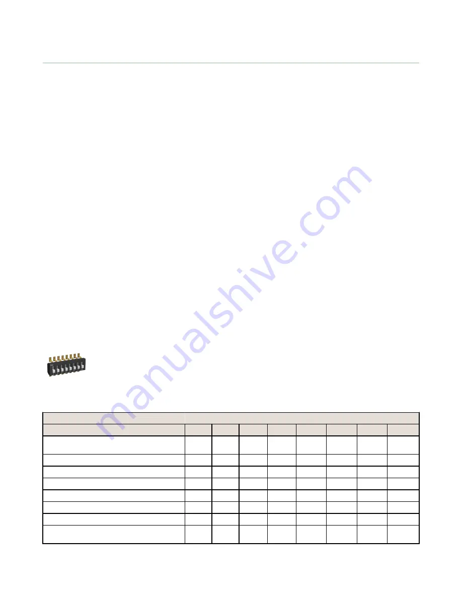
1. If your radios have DIP switches, configure the DIP switches of all devices.
2. Connect the sensors to the MultiHop radios if applicable.
3. Apply power to all devices.
4. If your MultiHop radio has rotary dials, set the MultiHop Radio (Slave) ID. If your MultiHop radio has no rotary dials,
continue to the next step.
5. Form the wireless network by binding the slave and repeater radios to the master radio. If the binding instructions are
not included in this datasheet, refer to the product manual for the binding instructions.
6. Observe the LED behavior to verify the devices are communicating with each other.
7. Conduct a site survey between the MultiHop radios. If the site survey instructions are not included in this datasheet,
refer to the product manual for detailed site survey instructions.
8. Install your wireless sensor network components. If the installation instructions are not included in this datasheet, refer
to the product manual for detailed installation instructions.
For additional information, including installation and setup, weatherproofing, device menu maps, troubleshooting, and a
list of accessories, refer to one of the following product manuals.
•
MultiHop Radio Quick Start Guide:
•
MultiHop Radio Product Manual:
•
MultiHop Register Guide (End User Edition):
Configure the DIP Switches
Before making any changes to the DIP switch positions, disconnect the power. DIP switch changes will not be recognized if
power isn't cycled to the device.
Accessing the Internal DIP Switches
To access the internal DIP switches, follow these steps:
1. Unscrew the four screws that mount the cover to the bottom housing.
2. Remove the cover from the housing without damaging the ribbon cable or the pins the cable plugs into.
3. Gently unplug the ribbon cable from the board mounted into the bottom housing.
4. Remove the black cover plate from the bottom of the device's cover.
The DIP switches are located behind the rotary dials.
After making the necessary changes to the DIP switches, place the black cover plate back into
position and gently push into place. Plug the ribbon cable in after verifying that the blocked hole
lines up with the missing pin. Mount the cover back onto the housing.
DIP Switch Settings (MultiHop)
Switches
Device Settings
1
2
3
4
5
6
7
8
Serial line baud rate 19200 OR User defined
receiver slots
OFF*
OFF*
Serial line baud rate 38400 OR 32 receiver slots
OFF
ON
Serial line baud rate 9600 OR 128 receiver slots
ON
OFF
Serial line baud rate Custom OR 4 receiver slots
ON
ON
Parity: None
OFF*
OFF*
Parity: Even
OFF
ON
Parity: Odd
ON
OFF
Disable serial (low power mode) and enable the
receiver slots select for switches 1-2
ON
ON
SureCross MultiHop Data Radio
P/N 148947 Rev. C
www.bannerengineering.com - tel: 763-544-3164
3