


1. Confirm the network connections.
a) Click the Start button, then on the Start menu, click Control Panel.
b) In Control Panel, click Network and Internet, then click Network and Sharing Center, and then click Change adapter settings.
c) Right-click on the connection that you want to change, then click Properties.
If you are prompted for an administrator password or confirmation, enter the password or provide confirmation.
d) In the connection properties, click Internet Protocol Version 4 (TCP/IPv4), and then click Properties.
e) In the Internet Protocol (TCP/IPv4) Properties, select Use the following IP address.
f)
Make sure that the IP address is 192.168.0.2, and the subnet mask is 255.255.255.0.
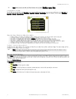
2. Open Vision Manager from the desktop or the Start menu.
The Sensor Neighborhood tab displays and lists the available sensors.
3.
From Sensor Neighborhood, click
to connect to the desired sensor.
The status changes from Available
to Connected
and the
Sensor screen displays. Click
to disconnect from the sensor.
4. If the desired sensor is not listed, verify that:
•
The network adapter connected to the sensor has the same subnet mask as the sensor (for example, 192.168.0.xxx); view the subnet
mask in the Network Adapters list at
Home > Sensor Neighborhood > Network Adapters
•
The Ethernet cable is the correct type
•
The TCP/IPv4 settings are correct
Or, manually enter the sensor's IP address.
Note: The sensor's IP address and subnet mask are also available from the sensor display.
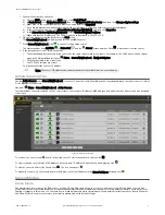
Active Sensors Tab
Use the Active Sensors tab in Sensor Neighborhood to connect to an active sensor. Available options vary depending on the type of sensor to which
Vision Manager is connected.
Navigate:
Home > Sensor Neighborhood > Active Sensors.
This tab includes sensor information such as sensor status, sensor name, IP address, MAC address, and model number. Sensors can also be added
to Favorites.
Figure 4. Active Sensors Tab
To connect to a sensor, click
next to the desired sensor. To disconnect from a sensor, click
.
To view or change sensor Status, MAC Address, Sensor Name, IP Address, Subnet Mask, and Gateway, click
.
To add the sensor to a Favorites Group, click
. The icon changes to
.
To manually connect to a sensor with a known IP address, enter the IP address in the Enter IP Address field and click
.
Sensor Modes
Demo Mode
The first time you power up the iVu BCR sensor, it starts in Demo Mode and allows you to choose whether to stay in Demo Mode or exit to Live
Mode. Demo Mode uses stored images and inspection parameters that demonstrate how the sensor is set up without having to worry about focus,
lighting, or triggers. In this mode, you can learn how to make adjustments while observing how the adjustments affect the sensor results. When you
exit Demo Mode, the sensor reboots into its normal operating mode with default settings.
iVu Plus BCR Gen2 Series Sensor
P/N 178443 Rev. C
www.bannerengineering.com - Tel: +1-763-544-3164
3