


35
Banner Engineering Corp.
•
Minneapolis, U.S.A.
www.bannerengineering.com • Tel: 763.544.3164
P/N 64118 rev. B
A.2.1 ASCII Format Data Transmission
There are two ways to use ASCII format to represent data. The one used depends upon
which measurement modes are selected.
For ALL measurement mode
, each data byte is presented in an eight-bit ASCII format
that conveys the status of four consecutive channels (four consecutive beams). Each
subsequent byte conveys the status of the next four channels, until the status of every
channel is reported. The allowable data values for All measurement mode are ASCII
numbers 0 to 9 and ASCII letters A to F. In the table, a ‘0’ represents an unblocked
beam channel, and ‘1’ represents a blocked channel.
For example, assume that a 64-channel system has been configured for the All
measurement Serial transmission option. Channels 1 through 4 are blocked, as is
channel 63. The serial string starts with 0x1c, and the ID (assume an ‘A’) followed by
16 ASCII values and terminated with 0x0A. The string would appear:
0x1c, ‘A’, ‘F’, ‘0’,’0’, ‘0’,’0’, ‘0’,’0’, ‘0’,’0’, ‘0’,’0’, ‘0’,’0’, ‘0’,’0’, ‘0’,’4’, 0x0a
The string shows that beams 1 through 4 are blocked, as is beam 63. All other beams
are unblocked. If the user had requested suppression of the header, then 0x1c, ‘A’, and
the 0x0a would have been deleted.
For transmitting Measurement mode data
, use three ASCII bytes to represent each
measurement mode. For example, if Meas1 is FBB, Meas2 is LBB, the measured values
are 6 and 120, and the controller ID is B, the data string is as follows:
0x1c ‘B’, ‘0’, ‘0’, ‘6’, ‘1’, ‘2’, ‘0’, 0x0a
As with ALL mode, the header and clear data could be suppressed. For clear data
suppression, the control module sends the status of a clear condition only on the first
“clear” scan. After that, the control module will continue to scan but will not transmit
data until the sensor is again blocked.
A.2.2 Binary Format Data Transmission
Similar to ASCII format, binary format may be used to represent data in two ways. One
method involves the All Data transmission mode; the other, Measurement mode.
For All Data transmission mode
, the control module represents the status of eight
consecutive data channels for each byte. Each bit of each byte is directly related to the
status of an individual channel. The first data byte represents channels 1 through 8; the
second data byte represents channels 9 through 16. The bit pattern for the first and
second data bytes is as shown in Figure A-3.
For each bit position, 1 represents a blocked beam and 0 represents an unblocked
beam.
For example, for a 64-channel system with beams 1-6 blocked, beam 43 blocked and
beams 62-64 blocked, the data transmitted from control module ‘A’ is as follows:
0x1c, ‘A’, 0xFC, 0x00, 0x00, 0x00, 0x00, 0x20, 0x00, 0x07, 0x0A
This string would have the start byte, controller ID, followed by the eight data bytes
and terminated with the 0x0A. The header bytes may be suppressed if necessary.
Appendix A: Data Transmission
Banner Engineering Corp.
•
Minneapolis, U.S.A.
www.bannerengineering.com • Tel: 763.544.3164
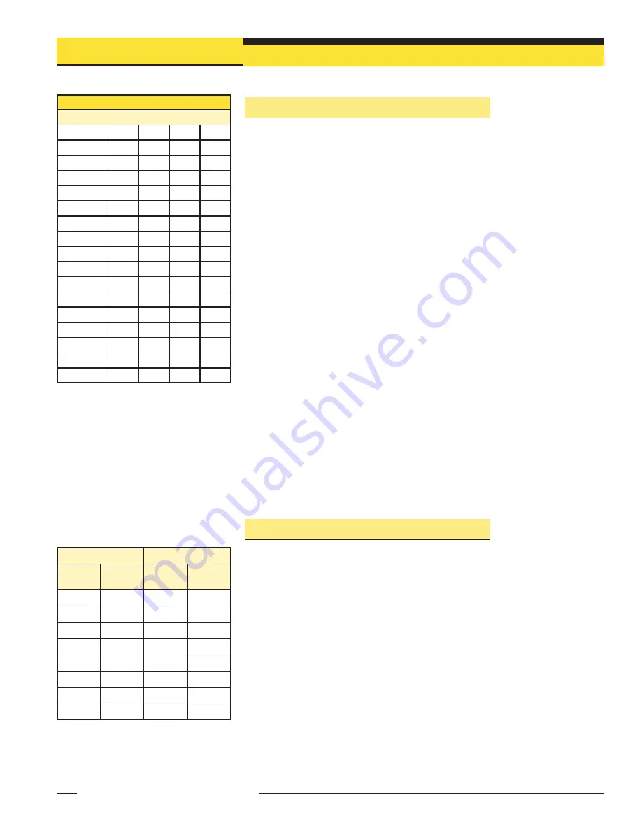
Figure A-2. ASCII data values
Definitions for ASCII Data Values
For the ALL measurement mode
Character
Ch 4
Ch3
Ch2
Ch1
F
1
1
1
1
E
1
1
1
0
D
1
1
0
1
C
1
1
0
0
B
1
0
1
1
A
1
0
1
0
9
1
0
0
1
8
1
0
0
0
7
0
1
1
1
6
0
1
1
0
5
0
1
0
1
4
0
1
0
0
3
0
0
1
1
2
0
0
1
0
1
0
0
0
1
0
0
0
0
0
First Data Byte
Second Data Byte
Channel
Bit
Position
Channel
Bit
Position
1
7
9
7
2
6
10
6
3
5
11
5
4
4
12
4
5
3
13
3
6
2
14
2
7
1
15
1
8
0
16
0
Figure A-3. Binary data values


