23
Banner Engineering Corp.
•
Minneapolis, U.S.A.
www.bannerengineering.com • Tel: 763.544.3164
P/N 64118 rev. B
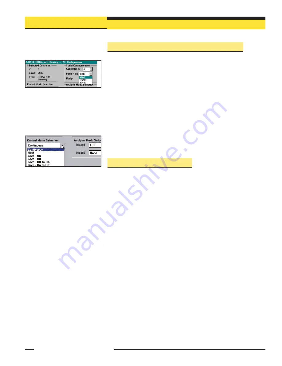
5.3.1 Selected Controller and Serial Communication
The Selected Controller box displays information about the control module being
configured. Two of these settings may be changed in the Serial Communication box.
The settings selected and displayed in these boxes are those used to identify the
control module during the Ping routine (section 5.1.1).
Controller ID
(assigned a letter, ‘
A
’ through ‘
O
’) is used to identify each individual
control module when multiple discrete-output control modules (up to 15) are
connected on one EIA-485 “party line.” NOTE: Analog output control modules do not
offer RS-485 communication; choose any ID letter (‘
A
’ through ‘
O
’) when programming
an analog-output control module.
Baud Rate
is the data communication rate between the control module and the
computer used for configuration and also the process controller. Choose from three
values:
9600, 19200,
and
38400
.
Parity:
Select
Odd
,
Even
, or
None
. All controllers on one EIA-485 party line should
have the same parity settings.
5.3.2 Control Mode Selection
The control mode determines the method used to control scanning of the light screen
array (see Figure 5-11). Choose from three main control modes:
• Continuous Scan mode,
• Serial Host Command mode, and
• Gate mode (which itself has four options)
In Continuous Scan Mode
, the control module begins a new scan as soon as it
updates the outputs from the previous scan. This is the fastest scan control method; it
is used in most analog output applications and whenever continuous updating of the
outputs is acceptable.
Host Mode
allows the control module to communicate with a host computer or control
module via RS-232 (all models) or RS-485 (discrete-output models only) serial
protocol. The host directs the control module to scan on demand and receives the
output data from the control module in binary or ASCII form. Baud rates of 9600,
19200, and 38400 are selectable in the Serial communications menu (section 5.3.1).
(See Appendix A for more information on Host mode data format.)
Gate Mode
activates an optically isolated external Gate input between terminals 12 (+)
and 13 (-) of the control module. The Gate input has impedance of 7.5 k
Ω
and accepts
a 10 to 30V dc signal. A dc device such as a photoelectric sensor or optical encoder
typically supplies the Gate input. Gate input signals must be greater than 150
microseconds in duration; the time between successive Gate inputs must be greater
than the minimum scan time for the light screen array (see section 5.3.3 for scan time
information).
Gate mode has four options:
• Gate ON:
the control module will scan as long as the gate is active.
• Gate OFF:
the control module will scan whenever the gate is not active.
• Gate ON/OFF:
the control module will scan once for each gate transition from ON to OFF.
•
Gate OFF/ON:
the control module will scan once for each gate transition from OFF to ON.
Figure 5-11. Control Mode selections
(PSF Configuration screen)
Figure 5-10. Selected Controller and Serial
Communication
selections (PSF Configuration
screen)
Control Module Configuration
Banner Engineering Corp.
•
Minneapolis, U.S.A.
www.bannerengineering.com • Tel: 763.544.3164


