Technical data
26
Panel PC 2100 user's manual V1.17
2.2.1.2 Installation diagrams
Information:
When installing the Panel PC 2100, be sure to leave sufficient space for air circulation as well as addi-
tional space for operation and maintenance of the device.
AP9x3 panels - Installation diagrams
Y
X
Z
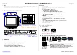
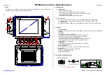
Figure 5: Panel PC 2100 with AP9x3 panels (sample figure) - Installation diagram
All dimensions are specified in mm.
The cutout tolerances are +0 mm / -0.5 mm.
Display type
Model number
X
Y
Z min.
Z max.
Number of retaining clips
12.1" single-touch
5AP923.1215-00
304
228
1
6
10 pcs.
15.0" single-touch
5AP923.1505-00
359
277
1
6
10 pcs.
19.0" single-touch
5AP923.1906-00
429
347
1
6
12 pcs.
15.6" multi-touch
5AP933.156B-00
403
247.5
1
6
10 pcs.
18.5" multi-touch
5AP933.185B-00
464
284
1
6
10 pcs.
21.5" multi-touch
5AP933.215C-00
530.5
322
1
6
14 pcs.
24.0" multi-touch
5AP933.240C-00
587.5
353
1
6
14 pcs.
Table 12: AP9x3 panels - Installation diagrams
Dimension "Z" describes the thickness of the wall or control cabinet panel.
A hex screwdriver is needed to tighten and remove the screws on the retaining clips. The maximum tightening
torque of the retaining clips is 1 Nm.


