background image

Technical data  • 8JSA3 - Technical data

36

8JSA user's manual V1.00

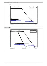
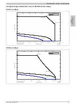
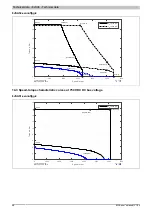
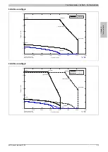
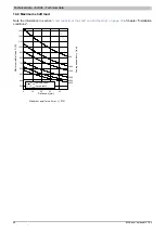
12.4 Maximum shaft load

Note the information in section 

"Load capacity of the shaft end and bearing" on page 70

 of chapter "Installation

conditions".

0

5

10

15

20

25

150

200

250

300

350

400

450

500

550

500

1000

1500

3000
4500

6000

Distance x [mm]

Pe

rm

is

si

bl

ra

di

al

 fo

rc

F

r

 [N

]

Maximum axial force: F

amax

 = 48 N

F

rmax

 (Smooth shaft)

F

rmax

 (Keyed shaft)

Av

er

ag

sp

ee

n

av

g

 [r

pm

]
Summary of Contents for 8JSA2 Series

Page 1: ...without notice B R Industrial Automation GmbH is not liable for technical or editorial errors and defects in this manual In addition B R Industrial Automation GmbH assumes no liability for damages th...

Page 2: ...d 21 9 Special motor options gg 21 10 General motor data 22 10 1 Reduction of nominal values depending on the motor option 23 10 2 Formula symbols 24 10 3 Power dissipation 25 11 8JSA2 Technical data...

Page 3: ...16 5 8JSA7 Dimensions 66 Chapter 3 Transport and storage 67 Chapter 4 Installation conditions 69 1 Installation and cooling 69 2 Load capacity of the shaft end and bearing 70 Chapter 5 Installation a...

Page 4: ...Table of contents 4 8JSA user s manual V1 00 Chapter 8 Standards guidelines and certifications 96 Chapter 9 Disposal 97 1 Safety 97 1 1 Protective equipment 97 1 2 Rotor with rare earth magnets 97...

Page 5: ...ccessible and stored in the immediate vicinity of the machine In addition to the information in this manual local accident prevention regulations and national industrial safety regulations apply Infor...

Page 6: ...lly high safety measures death injury severe physical im pairments or other serious losses are possible Do not use the product in the following areas as well as other areas associated with fatal risks...

Page 7: ...nly connect measuring instruments when the power is switched off Danger due to electromagnetic fields Electromagnetic fields are generated by the operation of electrical power engineering equipment su...

Page 8: ...Such incorrect behavior can be triggered by Incorrect installation or faults when handling components Improper or incomplete wiring Defective devices servo drive motor position encoder cables brake In...

Page 9: ...or operation of the finished system with motors gearboxes servo drives etc including safety notices To regularly check whether the operating instructions and manuals issued correspond to current rules...

Page 10: ...ions from a single source requires the right components as well as the right configuration for the application environment The large selection of available 8JS three phase synchronous motors makes it...

Page 11: ...ible at all times The nameplate is not permitted to be removed from the motor 4 1 1 Embedded parameter chip All relevant mechanical and electrical information and data is stored in the EnDat encoder u...

Page 12: ...k unit Star connected three phase winding Small construction volume thus low weight Minimized moments of inertia due to favorable rotor design thus very good dynamic properties High overload capabilit...

Page 13: ...18 1 100 rpm 020 2 000 rpm 023 2 250 rpm 024 2 400 rpm 025 2 500 rpm 028 2 750 rpm 030 3 000 rpm 035 3 500 rpm 040 4 000 rpm 045 4 500 rpm 050 5 000 rpm 055 5 500 rpm 080 8 000 rpm see Nominal speed n...

Page 14: ...brake keyed shaft and connection direction is D3 The model number for the necessary motor is therefore 8JSA44 E6040D300 0 2 2 Example order 2 A three phase synchronous motor type 8JSA54 with a nomina...

Page 15: ...wer data The sizes are distinguished by a number c in the model number The larger this number the larger the flange dimensions and power data of the respective motor Availability Cooling type Availabl...

Page 16: ...re the motor covers several revolutions for positioning a multi turn encoder that can save up to 65535 revolutions can be used A solution with a single turn encoder variant with a homing procedure is...

Page 17: ...our servo drives or inverter modules ACOPOS V2 090 or later ACOPOSmulti V2 031 or later Encoder type Order code E6 E7 Operating principle Optical Optical EnDat protocol 2 1 2 1 Functional safety Sing...

Page 18: ...d length Availability Size Lengths 8JSAx1 8JSAx2 8JSAx3 8JSAx4 8JSAx5 8JSA2 8000 8000 8JSA3 5000 3000 5500 4500 8JSA4 3500 5000 4000 8JSA5 4500 4500 2750 5000 8JSA6 3000 2250 3000 2500 8JSA7 2000 2400...

Page 19: ...ation com 8 2 Oil seal All 8JSA three phase synchronous motors are available with a form A oil seal per DIN 3760 When equipped with an oil seal the motors have IP65 protection per EN 60034 5 Motor opt...

Page 20: ...d to assume a safety factor of 2 Warning The holding brake is not intended for normal braking The holding brake does not provide protection for personnel The maximum motor torque far exceeds the holdi...

Page 21: ...hub connection and for handling torque in a constant direction The keyways for the 8JS three phase synchronous motors conform to keyway form N1 per DIN 6885 1 Form A keyed shafts that conform to DIN...

Page 22: ...ient temperature during operation 5 C to 40 C 3 Relative humidity during operation 5 to 95 non condensing Maximum ambient temperature during operation 40 C 3 Reduction of the nominal current and stall...

Page 23: ...071 0 071 0 191 0 191 8JSA43 Exnnnffgg 0 0 2 0 2 0 55 0 55 0 271 0 271 0 621 0 621 8JSA44 R0nnnffgg 0 0 12 0 12 0 071 0 071 0 191 0 191 8JSA44 Exnnnffgg 0 0 3 0 3 0 76 0 76 0 371 0 371 0 831 0 831 8JS...

Page 24: ...constant KT Nm A The torque constant specifies the torque generated by the motor at 1 Arms phase current This value applies at a motor temperature of 20 C If the temperature increases the torque cons...

Page 25: ...Free convection The motor data specified for the nominal operating point apply to a motor installed in a thermally open system The dimensions of the flange plates used for the measurement are shown in...

Page 26: ...8 7 Electrical time constant tel ms 1 8 2 1 Thermal time constant ttherm min 9 11 Moment of inertia J kgcm2 0 16 0 27 Weight without brake m kg 1 1 1 66 Holding brake Holding torque of brake MBr Nm 1...

Page 27: ...5638 0 0 1 41 TChar version 0124 DB version 2017 09 18 dT 100K dT 60K dT 60K nN 8000 rpm 11 2 Speed torque characteristic curves at 560 VDC DC bus voltage 8JSA22 eennnffgg 0 0 1000 2000 3000 4000 500...

Page 28: ...05 0 1 41 8000 1 06 TChar version 0124 DB version 2017 09 18 dT 100K dT 60K dT 60K nN 8000 rpm 11 3 Speed torque characteristic curves at 750 VDC DC bus voltage 8JSA22 eennnffgg 0 0 1000 2000 3000 400...

Page 29: ...000 1 06 TChar version 0124 DB version 2017 09 18 dT 100K dT 60K dT 60K nN 8000 rpm 11 4 Maximum shaft load Note the information in section Load capacity of the shaft end and bearing on page 70 of cha...

Page 30: ...er feedback Extension of K0 and K1 depending on the mo tor option mm Encoder assignments R0 E4 E5 E8 E9 Model number K0 K1 M Holding brake 8JSA21 eennnffgg 0 95 4 95 4 76 1 34 1 8JSA22 eennnffgg 0 114...

Page 31: ...10 3 9 01 Stator inductance L2ph mH 37 5 46 5 20 1 18 5 Electrical time constant tel ms 1 8 2 2 1 Thermal time constant ttherm min 14 17 20 Moment of inertia J kgcm2 0 33 0 59 0 85 Weight without brak...

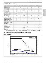
Page 32: ...7 8 9 Torque in Nm 0 8 2 589 8 2 2562 0 0 2 0 8 2 1384 8 3 3899 0 0 2 TChar version 0124 DB version 2017 09 18 dT 100K dT 60K nN 3000 rpm nN 5500 rpm 8JSA33 eennnffgg 0 0 500 1000 1500 2000 2500 3000...

Page 33: ...5 2 2 5 3 3 5 4 4 5 5 Torque in Nm 0 4 5 3046 4 5 5000 2 373 7340 0 0 1 15 5000 0 95 TChar version 0124 DB version 2017 09 18 dT 100K dT 60K dT 60K nN 5000 rpm 8JSA32 eennnffgg 0 0 1000 2000 3000 4000...

Page 34: ...9 4500 2 29 TChar version 0124 DB version 2017 09 18 dT 100K dT 60K dT 60K nN 4500 rpm 12 3 Speed torque characteristic curves at 750 VDC DC bus voltage 8JSA31 eennnffgg 0 0 1000 2000 3000 4000 5000 6...

Page 35: ...2962 8 2 3000 8 149 5537 0 0 2 3000 1 81 0 8 2 4941 8 3 5500 7 161 8100 2 432 0 2 5500 1 6 TChar version 0124 DB version 2017 09 18 dT 100K dT 60K nN 3000 rpm nN 5500 rpm 8JSA33 eennnffgg 0 0 1000 20...

Page 36: ...ction Load capacity of the shaft end and bearing on page 70 of chapter Installation conditions 0 5 10 15 20 25 150 200 250 300 350 400 450 500 550 500 1000 1500 3000 4500 6000 Distance x mm Permissibl...

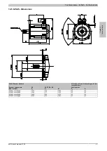
Page 37: ...37 12 5 8JSA3 Dimensions K K EnDat Resolver feedback Extension of K0 and K1 depending on the mo tor option mm Encoder assignments R0 E4 E5 E8 E9 Model number K0 K1 M Holding brake 8JSA31 eennnffgg 0 1...

Page 38: ...ductance L2ph mH 26 8 10 8 11 5 Electrical time constant tel ms 3 4 3 8 4 1 Thermal time constant ttherm min 17 20 24 Moment of inertia J kgcm2 1 5 2 1 2 7 Weight without brake m kg 3 39 4 35 5 3 Hold...

Page 39: ...eed in rpm 0 5 10 15 20 25 Torque in Nm 0 18 8 1476 18 8 3600 0 0 4 8 TChar version 0124 DB version 2017 09 18 dT 100K dT 60K dT 60K nN 5000 rpm 8JSA44 eennnffgg 0 0 500 1000 1500 2000 2500 3000 3500...

Page 40: ...rpm 0 2 4 6 8 10 12 14 Torque in Nm 0 13 1 1953 13 1 3500 5 657 4945 0 0 3 42 3500 2 74 TChar version 0124 DB version 2017 09 18 dT 100K dT 60K dT 60K nN 3500 rpm 8JSA43 eennnffgg 0 0 1000 2000 3000 4...

Page 41: ...11 075 5222 0 0 5 88 4000 3 69 TChar version 0124 DB version 2017 09 18 dT 100K dT 60K dT 60K nN 4000 rpm 13 3 Speed torque characteristic curves at 750 VDC DC bus voltage 8JSA42 eennnffgg 0 0 1000 2...

Page 42: ...18 8 4148 18 8 5000 14 629 6100 10 177 0 4 8 5000 2 94 TChar version 0124 DB version 2017 09 18 dT 100K dT 60K dT 60K nN 5000 rpm 8JSA44 eennnffgg 0 0 1000 2000 3000 4000 5000 6000 7000 Speed in rpm...

Page 43: ...tion in section Load capacity of the shaft end and bearing on page 70 of chapter Installation conditions 0 10 20 30 300 400 500 600 700 800 900 1000 1100 1200 1300 500 1000 1500 3000 4500 6000 Distanc...

Page 44: ...feedback Extension of K0 and K1 depending on the mo tor option mm Encoder assignments R0 E6 E7 EA EB Model number K0 K1 M Holding brake 8JSA41 eennnffgg 0 118 8 136 8 96 4 33 5 8JSA42 eennnffgg 0 147...

Page 45: ...ance R2ph 1 16 1 45 1 58 0 65 Stator inductance L2ph mH 5 2 7 8 9 6 3 5 Electrical time constant tel ms 4 5 5 4 6 1 5 4 Thermal time constant ttherm min 20 24 31 Moment of inertia J kgcm2 3 4 6 2 12 W...

Page 46: ...que in Nm 0 29 9 1444 29 9 3071 0 0 8 5 TChar version 0124 DB version 2017 09 18 dT 100K dT 60K dT 60K nN 4500 rpm 8JSA54 eennnffgg 0 0 500 1000 1500 2000 2500 3000 3500 Speed in rpm 0 10 20 30 40 50...

Page 47: ...Speed in rpm 0 2 4 6 8 10 12 14 16 18 Torque in Nm 0 15 7 4758 15 699 4500 15 699 6100 11 018 0 4 83 4500 2 89 TChar version 0124 DB version 2017 09 18 dT 100K dT 60K dT 60K nN 4500 rpm 8JSA52 eennnff...

Page 48: ...3155 53 9 5000 15 413 5487 0 0 14 4 5000 6 92 TChar version 0124 DB version 2017 09 18 dT 100K dT 60K nN 2750 rpm nN 5000 rpm 14 3 Speed torque characteristic curves at 750 VDC DC bus voltage 8JSA51 e...

Page 49: ...4500 25 628 6100 12 562 0 8 5 4500 5 02 TChar version 0124 DB version 2017 09 18 dT 100K dT 60K dT 60K nN 4500 rpm 8JSA54 eennnffgg 0 0 1000 2000 3000 4000 5000 6000 7000 Speed in rpm 0 10 20 30 40 5...

Page 50: ...n Load capacity of the shaft end and bearing on page 70 of chapter Installation conditions 0 10 20 30 40 300 400 500 600 700 800 900 1000 1100 1200 1300 500 1000 1500 3000 4500 6000 Distance x mm Maxi...

Page 51: ...at Resolver feedback Extension of K0 and K1 depending on the mo tor option mm Encoder assignments R0 E6 E7 EA EB Holding brake Model number K0 K1 M K0 K1 8JSA51 eennnffgg 0 127 5 146 105 3 45 43 8JSA5...

Page 52: ...0 75 0 73 Stator inductance L2ph mH 13 4 14 6 6 2 6 1 Electrical time constant tel ms 8 1 8 6 8 3 8 4 Thermal time constant ttherm min 20 25 30 35 Moment of inertia J kgcm2 17 24 2 32 40 Weight withou...

Page 53: ...ed in rpm 0 10 20 30 40 50 60 70 Torque in Nm 0 59 3 708 59 3 1665 0 0 16 8 TChar version 0124 DB version 2017 09 18 dT 100K dT 60K dT 60K nN 2250 rpm 8JSA64 eennnffgg 0 0 500 1000 1500 2000 2500 Spee...

Page 54: ...25 TChar version 0124 DB version 2017 09 18 dT 100K dT 60K dT 60K nN 2500 rpm 15 2 Speed torque characteristic curves at 560 VDC DC bus voltage 8JSA62 eennnffgg 0 0 500 1000 1500 2000 2500 3000 3500...

Page 55: ...ue in Nm 0 59 3 1390 59 3 2250 26 312 2895 0 0 16 8 2250 13 61 TChar version 0124 DB version 2017 09 18 dT 100K dT 60K dT 60K nN 2250 rpm 8JSA64 eennnffgg 0 0 500 1000 1500 2000 2500 3000 3500 4000 45...

Page 56: ...0 51 474 3362 0 0 25 2500 19 TChar version 0124 DB version 2017 09 18 dT 100K dT 60K dT 60K nN 2500 rpm 15 3 Speed torque characteristic curves at 750 VDC DC bus voltage 8JSA62 eennnffgg 0 0 1000 2000...

Page 57: ...que in Nm 0 59 3 2051 59 3 2250 52 34 3598 0 0 16 8 2250 13 61 TChar version 0124 DB version 2017 09 18 dT 100K dT 60K dT 60K nN 2250 rpm 8JSA64 eennnffgg 0 0 500 1000 1500 2000 2500 3000 3500 4000 45...

Page 58: ...19 TChar version 0124 DB version 2017 09 18 dT 100K dT 60K dT 60K nN 2500 rpm 15 4 Maximum shaft load Note the information in section Load capacity of the shaft end and bearing on page 70 of chapter I...

Page 59: ...ver feedback Extension of K0 and K1 depending on the mo tor option mm Encoder assignments R0 E6 E7 EA EB Holding brake Model number K0 K1 M K0 K1 8JSA62 eennnffgg 0 153 7 172 2 130 5 47 47 5 8JSA63 ee...

Page 60: ...ance L2ph mH 10 8 5 9 7 7 Electrical time constant tel ms 15 7 15 5 16 4 Thermal time constant ttherm min 46 53 60 Moment of inertia J kgcm2 65 92 120 Weight without brake m kg 19 7 26 7 33 6 Holding...

Page 61: ...rpm 0 20 40 60 80 100 120 140 160 180 Torque in Nm 0 167 9 731 167 9 1679 0 0 41 6 TChar version 0124 DB version 2017 09 18 dT 100K dT 60K dT 60K nN 2400 rpm 8JSA74 eennnffgg 0 0 200 400 600 800 1000...

Page 62: ...80 100 120 140 Torque in Nm 0 119 3 1147 119 3 2000 49 529 2667 0 0 30 2000 23 4 TChar version 0124 DB version 2017 09 18 dT 100K dT 60K dT 60K nN 2000 rpm 8JSA73 eennnffgg 0 0 500 1000 1500 2000 250...

Page 63: ...482 2186 0 0 52 5 1800 39 3 TChar version 0124 DB version 2017 09 18 dT 100K dT 60K dT 60K nN 1800 rpm 16 3 Speed torque characteristic curves at 750 VDC DC bus voltage 8JSA72 eennnffgg 0 0 500 1000 1...

Page 64: ...orque in Nm 0 167 9 1942 167 898 2400 123 349 3629 0 0 41 6 2400 28 2 TChar version 0124 DB version 2017 09 18 dT 100K dT 60K dT 60K nN 2400 rpm 8JSA74 eennnffgg 0 0 500 1000 1500 2000 2500 3000 Speed...

Page 65: ...the information in section Load capacity of the shaft end and bearing on page 70 of chapter Installation conditions 0 20 40 60 1000 1500 2000 2500 500 1000 1500 3000 4500 6000 Distance x mm Permissib...

Page 66: ...nDat Resolver feedback Extension of K0 and K1 depending on the mo tor option mm Encoder assignments R0 E6 E7 EA EB Holding brake Model number K0 K1 M K0 K1 8JSA72 eennnffgg 0 192 5 201 7 164 5 42 51 6...

Page 67: ...an extent that the braking effect is non existent or reduced Similarly encoder errors or damage to the gearbox can occur as a result Transport and store the product only in its original packaging and...

Page 68: ...avoid damage during storage Reduce the storage time to a minimum and do not exceed the maximum storage time of 2 years Rotate the motor shaft a few turns at least every 6 months either by hand or at...

Page 69: ...ntinuous operation of the servo motors at an ambient temperature of 40 C to max 45 C is possible but this results in premature aging 2 Requirements that go beyond this must be arranged with B R 3 With...

Page 70: ...the loads during installation e g belt tension on pulleys and operation e g load torque on the pinion The maximum radial force Fr depends on the shaft end type bearing type average speed the position...

Page 71: ...he shaft end and bearing Chapter 4 Installation conditions 8JSA user s manual V1 00 71 x Fr Fa Figure 1 Definition of shaft load Fr Radial force Fa Axial force x Distance between the motor flange and...

Page 72: ...be negatively affected and dangers can arise Due to this severe damage to property and injuries cannot be excluded Unauthorized modifications are therefore prohibited Do not carry out any unauthorized...

Page 73: ...DC bus Only connect measuring instruments when the power is switched off Danger due to electromagnetic fields Electromagnetic fields are generated by the operation of electrical power engineering equi...

Page 74: ...e them Failure to comply with instructions guidelines and regulations or use of unsuitable or damaged tools and devices can result in serious injury and or damage to property Motors should only be lif...

Page 75: ...hot surfaces also during downtime Allow motor and gearbox to cool sufficiently before working on it This is because there is still a risk of burning for a prolonged period of time even after shutting...

Page 76: ...aring Avoid an overdetermined bearing when attaching drive elements onto the output shaft The necessarily occurring tolerances cause additional forces on the output shaft bearing This can damage or si...

Page 77: ...n overloaded during operation Before installation ensure that the motor or gearbox is suitable for the machine It is better not to carry out short term test and trial operations with damaged or inappr...

Page 78: ...is immediate danger of fatal electric shock If connections are connected or disconnected in the incorrect order or when the power is switched on electric arcs can occur and persons and contacts can b...

Page 79: ...see the current user s manual for the B R drive system being used They are available in the Downloads section of the B R website www br automation com 5 1 1 Cables from other manufacturers Caution Da...

Page 80: ...witched on Do not stay in the danger zone during operation and secure it against access by unauthorized persons Always operate the motor with all safety equipment Do this even during short testing and...

Page 81: ...ector from the motor 4 Disconnect the cable from the drive system ACOPOS 5 3 Connecting connectors properly The power and encoder connectors are available in different variants Caution Damage due to i...

Page 82: ...groove immediately after the fine thread Vibration ring order data Model number 8PX000 00 1 Model number 8PX001 00 1 50 piece anti vibration ring size 1 for speedtec connector 10 piece anti vibration...

Page 83: ...n 5 V output 0 25A Encoder power supply 5 V 8 Violet T Clock input 9 Yellow T Clock input inverted 10 White Green COM 1 3 9 11 13 15 0 V encoder power supply 11 12 Blue Black B Channel B 13 Red Black...

Page 84: ...evices are generally not failsafe Ensure that the motor is brought into a safe state if the servo drive fails 2 1 General sources of danger Tampering of protection or safety devices Protective and or...

Page 85: ...DC bus Only connect measuring instruments when the power is switched off Danger due to electromagnetic fields Electromagnetic fields are generated by the operation of electrical power engineering equi...

Page 86: ...e them Failure to comply with instructions guidelines and regulations or use of unsuitable or damaged tools and devices can result in serious injury and or damage to property Motors should only be lif...

Page 87: ...this can cause the shaft end to break which can lead to severe damage It is therefore preferable to use a smooth shaft during heavy reversing operation 2 3 Freely rotating motors With freely rotating...

Page 88: ...ections are tightened correctly Any unused connection threads on the flanged end shield are sealed All components attached to the output shaft are secured against unintentional release Shaft keys and...

Page 89: ...orm the responsible qualified personnel immediately 4 Faults during operation In the following table you can find possible causes of error broken down by malfunction as well as information about how t...

Page 90: ...If necessary contact B R For this the following information should be provided Order description and serial number see nameplate Type and extent of fault Circumstances under which the fault occurred...

Page 91: ...propriate equipment and tools Protect yourself with safety equipment Warning Personal injury and damage to property due to unauthorized modifications As a result of unauthorized modifications to the p...

Page 92: ...measuring instruments when the power is switched off Danger due to electromagnetic fields Electromagnetic fields are generated by the operation of electrical power engineering equipment such as trans...

Page 93: ...or severely injure them Failure to comply with instructions guidelines and regulations or use of unsuitable or damaged tools and devices can result in serious injury and or damage to property Motors...

Page 94: ...again The brake test function in the ACOPOS servo drive used must be enabled During a refresh cycle the motor is allowed to turn one revolution at a speed of 50 rpm with the brake engaged This cleans...

Page 95: ...hout the entire service life of the motor 4 Cleaning Clean the motors regularly to ensure good heat dissipation Information During cleaning work hold the drive cable connector in place Remove fibers a...

Page 96: ...The motors correspond to the low voltage directive conformity EMC Directive 2014 30 EU To operate the motor in accordance with its intended use it must comply with the protection requirements of the...

Page 97: ...ion 1 2 Rotor with rare earth magnets In B R motors rotors are installed with rare earth magnets with high magnetic energy densities Warning Personal injury and damage to property due to rare earth ma...

Page 98: ...hing information 98 8JSA user s manual V1 00 Publishing information B R Industrial Automation GmbH B R Strasse 1 5142 Eggelsberg Austria Telephone 43 7748 6586 0 Fax 43 7748 6586 26 office br automati...

Reviews: