Commissioning
216
Panel PC 2200 built-in devices User's manual V 1.05 Translation of the original documentation
3.1.5 Installation information for separate shipments
Information:
If the Panel PC 2200 is not delivered as a complete system but as a separate shipment, or if individual
components are retrofitted, these components must be enabled in BIOS. To do this, launch BIOS during
system startup, load the BIOS default values and save the settings. For additional information, see
. This is required for the following individual components:
•
System unit
•
Panel
3.1.6 Replacing the system unit
1. Disconnect the power supply cable to the Panel PC (disconnect the power cable!). Disconnect from all sources
and poles!
2. Carry out electrostatic discharge at the ground connection.
3. Remove the Panel PC from the control cabinet by following the installation steps in reverse order.
4. Place the Panel PC on a clean, flat surface.
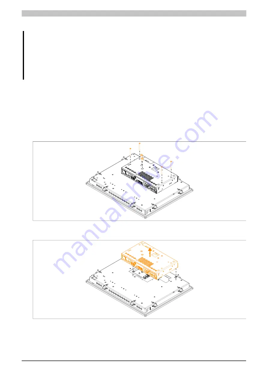
5. The Torx screws (T10) marked in the following figure must be removed, see also
Installation markings" on page 42
Figure 120: Removing the Torx screws
6. The system unit can now be removed by pulling upwards.
Figure 121: Removing the system unit
7. The system unit can be reinstalled in reverse order. The max. tightening torque of the Torx screws (T10) is
0.5 Nm.
Only the supplied installation materials are permitted to be used to install the system unit.


