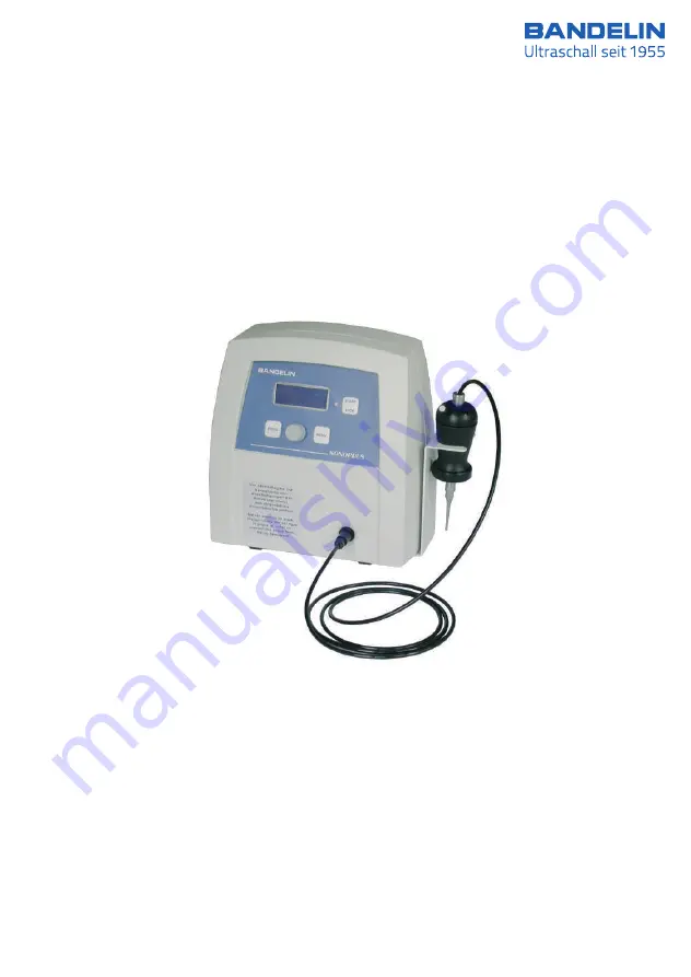
Ultrasonic Homogenizer mini20
7
Instructions for Use
51406c GB/2019-07
Page 1: ...Ultrasonic Homogenizer mini20 7 Ultrasonic Homogenizer mini20 Instructions for Use 51406c GB 2019 07 ...
Page 2: ...een the translation and the original of this document the original version has priority BANDELIN accepts no responsibility or liability for damages caused by improper handling or usage contrary to the intended purpose The documentation was prepared with great care Liability for indirect or direct damages arising because of incomplete or erroneous information in this documentation as well as in its...
Page 3: ...ity will be void If Service is required please contact the specialist dealer in charge or the manufacturer Symbols used Symbol Significance Explanation Danger Identifies information that could signify a risk to life and limb especially through electric shock if not observed Caution Identifies information that is to be observed and adhered to without fail to prevent damage to the device and danger ...
Page 4: ... 11 2 Preparation 12 2 1 Scope of delivery 12 2 2 Set up assembly 12 2 2 1 HF connection for the ultrasonic converter 13 2 3 Start up 13 3 Operation 14 3 1 Operating elements 14 3 1 1 Turning the homogenizer on off 15 3 1 2 Explanation of the display fields 15 3 2 Setting the operating parameters 15 3 2 1 Sonication time time 16 3 2 2 Pulsation pulse 17 3 2 3 Special functions 18 3 3 Loading savin...
Page 5: ...1 Maintenance 28 6 2 Functional checks 28 6 2 1 Testing the ultrasonic transducer probe check Error 011 28 6 2 2 Conducting a frequency scan scan frequency Error 002 011 012 28 6 3 Error analysis 30 6 4 Repairs and service 33 6 4 1 Decontamination certificate 33 6 4 2 Software version display 33 7 Accessories 34 7 1 Required accessories not applicable 34 7 2 Optional accessories 34 7 3 Preparation...
Page 6: ...omponents can be varied using a multitude of options and accessories The type specification and serial number are found on the type plate Product features HF generator 1 in low maintenance robust plastic housing with connections for the ultrasonic transducer 2 Operating and display panel 3 with LCD display 4 Ultrasonic transducer 5 with Start Stop button 5a and ventilation slits 5b Probe 6 Product...
Page 7: ...1 2 Purpose SONOPULS ultrasonic homogenizers generate high performance ultrasound with high intensities and ultrasonic amplitudes which are transferred into liquid media through working tools known as probes They are used in laboratories clinics and in industrial research and in the process they perform versatile tasks during sample preparation in Quality Assurance scientific experiments analyses ...
Page 8: ...ght 2 kg Protection class Class I Degree of protection IP 30 according to DIN 60529 2 Depending on the operating conditions and production tolerances as well as the probe types used the actual value of the resonance or ultrasonic frequency can deviate from the specified value 3 Depending on the operating conditions and production tolerances the actual value of the ultrasonic frequency can deviate ...
Page 9: ...or for information The homogenizer has been inspected pursuant to norms currently in effect and is to be installed and put into operation pursuant to EMC directions information in this respect is found in the appendix Specifications pursuant to the Medical Devices Operator Ordinance MPBetreibV Commissioning on site functional check and personnel instruction section 5 Not required Technical safety ...
Page 10: ...nterface application information are provided by the manufacturer on request For communication a commercially available infrared adapter RS 232 can be used The program related implementation required for communication is the responsibility of the user and is not supported by the manufacturer The manufacturer only guarantees proper functioning of the interface Optical access is located on the botto...
Page 11: ...d set up conditions see chapter 1 4 Determine the mains voltage before connecting the HF generator Only connect the HF generator to a grounded socket Fuse protection 10 A main circuit breaker The metallic ultrasonic transducer system must not be turned inside the black housing of the ultrasonic converter This would destroy the ultrasonic transducer system and its electrical connections The plastic...
Page 12: ...only be replaced with original parts or parts of the same quality 2 Preparation Carefully unpack the HF generator ultrasonic transducer and accessories and inspect them for completeness or possible transportation damages If any damages or defects are found these are to be immediately notified in writing to the transportation company and to the supplier Before startup the ultrasonic bath is to be l...
Page 13: ... grounded socket 2 2 1 HF connection for the ultrasonic converter The ultrasonic converter is connected to the HF generator by means of a push pull round plug MEDISNAP plug with lock For connection hold the plug on the handle and position it so that guide lug and arrow marking point upwards The plug can only be closed if the guide groove of the socket and the guide lug of the plug are positioned a...
Page 14: ...eaving the menu 3 PROG button Calling up the save options moving within the menu backward 4 Rotary knob Setting the operating parameters right left without dead stop 5 MENU button Calling up the list of editable operating parameters moving within the menu forward 6 Control LED 14 38 51406c GB 2019 07 1 electronic GmbH Co KG Heinrichstraße 3 4 12207 Berlin Deutschland info bandelin com 3 Operation ...
Page 15: ...omogenizer will display the manufacturer s name type designation and the last connected sonotrode probe If the probe type displayed does not conform with the probe that is mounted the correct probe type will have to be set before the next step using the rotary knob By pressing the START STOP button the menu switches into stand by mode and the ultrasonic homogenizer is ready for operation The param...
Page 16: ... Default values for the pulsation of the ultrasound turn on and turn off time pulse Limit value for the temperature monitoring C Operating mode for the ultrasound control En The operating parameters Energy and Elapsed sonication time cannot be edited 3 2 1 Sonication time time A value of 9 hours 59 minutes and 59 seconds 9 59 59 can be set as the maximum sonication time If the set value is exceede...
Page 17: ...0 5s 01 0s energy 0 000 kJ 01 0 Pulse switch off time 1 to 60 seconds Pulse switch off time 0 2 to 60 seconds START STOP 17 38 51406c GB 2019 07 1 electronic GmbH Co KG Heinrichstraße 3 4 12207 Berlin Deutschland info bandelin com 3 2 2 Pulsation pulse 1 In addition to the pulse turn on time tE and the pulse turn off time tA 2 additional operating modes can also be set off no pulsation or continuo...
Page 18: ... the HF generator for example cannot synchronise with the ultrasonic transducer and issues an error message e g Error 011 The HF frequency is reset to the base value and the function is restored if no device fault or other cause is present The set value is off In order to activate the function set the parameter to start using the rotary knob and then press the START STOP button See chapter 6 2 1 f...
Page 19: ...ether the ultrasonic homogenizer is to work with amplitude or power control ampl Amplitude control constant amplitude Thanks to the direct data logging in the ultrasonic transducer AMPLICHRON system the amplitude is precisely and quickly measured and set In the process the power output may fluctuate based on the physical state of the medium power power control constant power output The control var...
Page 20: ...ROG button and the content of the selected memory is displayed The sonication programmes can be individually selected using the rotary knob Memory location 0 represents the working memory Loading the sonication programme After selecting the desired sonication programme the parameters are transferred to the working memory by pressing the START STOP button and they can be used or processed in that l...
Page 21: ...nce between the specified and the actual value as well as a fluctuating display may occur The amplitude and the power can be changed at any time during ultrasound operation using the rotary knob All other operating parameters can only be edited while in stand by mode see chapter 3 2 If the ultrasound operation is manually interrupted before it reaches the activated target time the display values f...
Page 22: ... interface between the liquids to be mixed Do not use combustible solvents in open reaction vessels since the operating safety of the homogenizer could be compromised In order to shut down the device disconnect it from the mains pull the plug Remarks on cavitation formation Compared to those of the larger ultrasonic homogenizers the amplitudes for SONOPULS mini20 are much lower especially for smal...
Page 23: ...th small sample quantities and when immersing oscillating probes Step 5 Remove the sample After sonication the probes are to be removed from the medium Leaving them in the sonicating medium for a longer time can cause damage to the probe Once the programme or time setting has elapsed the delivery of ultrasound ends automatically If continuous sonication has been set the ultrasound delivery must be...
Page 24: ...e of delivery of the ultrasonic homogenizer or are supplied together with the probe Do not mechanically burden the probes during installation danger of bending Before mounting the probes the HF generator must be switched off or the ultrasonic converter separated from the HF generator Work steps for disassembly see illustration Place the ultrasonic converter on a level surface e g tabletop Push the...
Page 25: ...to the guide grooves Turn the ultrasonic converter and spanner to the right so that the other end of the lies on the surface and the coupling piece can no longer be turned to the right Screw in the probe hand tight Now push the spanner with width 8 into the guide grooves of the probe Then firmly screw on the probe In doing so firmly hold the spanner at the coupling piece If the coupling surface is...
Page 26: ... of erosion on the probe surface The surface of the probe can be refinished by the manufacturer only if the probe is qualified for after check up Cleaning disinfection of the ultrasonic converter Cleaning and disinfecting can be done by wiping Use only products on a aqueous alcoholic or peroxide base to clean and disinfect The ultrasonic converter may be wiped off Spraying or immersing in water fo...
Page 27: ... the sound emitting surfaces see chapter 5 1 Wear Therefore the sonicating parts such as the probes vessels and accessories are to be disinfected and cleaned and dismounted for this purpose if necessary after every use In the event of toxic contamination the applicable regulations and provisions of the BGR 250 TRBA 250 are especially to be observed The disinfection and cleaning should be performed...
Page 28: ...n out or faulty probes can be replaced following the instructions in chapters 4 3 1 The devices are calibrated at the time of delivery A control of the calibration is only required after repairs and is only conducted by the manufacturer 6 2 Functional checks See also chapter 3 2 3 for description and operation 6 2 1 Testing the ultrasonic transducer probe check Error 011 The test is preferably con...
Page 29: ...ise an error message such as Error 012 appears again IMPORTANT Only allow repairs to be conducted by authorised skilled personnel Kindly inform us in writing of any malfunctions use the enclosed questionnaire Important information Before each repair turn off the device and disconnect the plug from the mains Defective parts may only be replaced with original parts The black housing of the ultrasoni...
Page 30: ...r a high level of reliability Nevertheless the possibility of a malfunction due to a defective component can never be fully discounted Mechanical defects of the HF connector sockets the plug connectors the ultrasonic transducer etc are also possible as a result of frequent use or even incorrect handling e g by dropping them Critical faults are recognised by the device and signaled by a red LED and...
Page 31: ...eck function conduct a probe check or scan frequency If no success Repairs only through Customer Service Check the connection to the probe Is the cable properly plugged in and affi xed Is the probe correctly screwed on Check for erosion on the probe Once error rectifi ed conduct the probe check or scan frequency function see chapter 6 2 011 No response signal from the ultrasonic transducer 012 No ...
Page 32: ... erosion on the probe see chapter 5 1 slight Polish the probe some pitting Mill the probe until flat or grind max 1 mm heavy Replace the probe with new ones Has liquid seeped in between the ultrasonic transducer and the probe Dismount the probe clean the mounting surfaces and threads dry and check for evenness remount the probe and tighten see chapter 4 3 1 Is the threaded pin attachment on the ti...
Page 33: ...minated if necessary see the following chapter 6 4 1 Decontamination certificate If the homogenizer is sent back to the manufacturer for repairs with accessories if applicable the form Certificate of Decontamination is to be filled out and affixed to the packaging on the outside in a visible spot If this form has not been filled out we reserve the right to refuse receipt of the package in order to...
Page 34: ...btained from our supplier our sales representatives or from our website No obligation telephone consultation Website 49 0 30 768 80 0 www bandelin com 7 1 Required accessories not applicable 7 2 Optional accessories Pos Order no Designation 1 3639 Probe MS 1 5 2 3654 Probe MS 2 0 3 3652 Probe MS 2 5 7 3 Preparations not applicable 8 Consumable materials not applicable 9 Taking the unit out of serv...
Page 35: ...e 8 11 12 22 23 25 26 29 Defects 12 30 33 Degree of protection 8 10 Disinfection 26 27 E EMC 9 11 Emulsion 22 Energy 7 8 15 16 21 Environmental conditions 9 10 Error message 14 18 28 29 Error No 31 F Frequency control 8 Functioning 10 Fuse 6 11 32 H Handling 3 7 30 HF connection 8 11 13 HF frequency 18 HF generator 6 7 8 10 11 12 13 14 15 18 22 24 26 30 31 33 HF Generator 8 12 HF power 8 19 Holder...
Page 36: ...type 8 13 15 22 Product information 3 24 Protection class 8 Pulsation 16 17 18 Pulsation time 8 15 R Remote control 10 14 Repair 12 28 29 31 32 33 Resonance frequency 8 18 31 32 Round plug 8 10 13 26 S Scope of delivery 3 12 24 Setpoint 22 Signal tone 20 21 30 Software version 33 Solvents 11 22 Sonication 7 16 22 23 Sonication program 20 Sonication time 15 16 21 Sound emitting surface 26 27 28 Spa...
Page 37: ...BANDELIN electronic GmbH Co KG Heinrichstraße 3 4 12207 Berlin Deutschland www bandelin com info bandelin com 49 30 768 80 0 49 30 773 46 99 Zertifiziert nach ISO 9001 ISO 13485 ...
Page 38: ...Note The user instructions in this and other languages as well as further information can be found on the enclosed CD ...