12
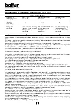
There should also be an adequate increase in combustion air to meet the increase in fuel delivery.
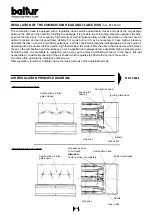
Adjustment can be carried out at first regulation by operating the screws which vary the profile of the commend disk
of the combustion air regulator. Fuel and combustion air delivery both increase at the same time until they reach
maximum value (fuel pressure at the return pressure regulator is equal to about 18 ÷ 20 bar if the pressure at the
pump is at the value of 20 ÷ 22 bar).
Fuel and combustion air delivery remain at maximum value until the boiler temperature (pressure, if steam boiler),
approaches the value at which it has been set and causes the modulation control servomotor to reverse its previous
sense of movement. The return movement of the modulation servomotor causes a reduction in fuel delivery and a
relative reduction in combustion air.
The modulation system reaches a position of equilibrium which corresponds to a fuel delivery and a relative combustion
air delivery equal to the quantity of heat required by the boiler.
With the boiler operating, the probe in the boiler is aware of load variations in the boiler and automatically requests the
modulation. Servomotor to make an adjustment in the fuel delivery and in the relative combustion air. Should the
maximum temperature (pressure, if steam boiler) be reached even with fuel and combustion air delivery at a minimum,
the thermostat (pressure switch, if steam boiler) will intervene when the value at which it has been set is reached, and
bring the burner to a standstill. When the temperature (pressure, if steam boiler) drops below the intervention limit of
the “shut down” device, the burner will start up again as previously described.
It should be kept in mind that the field of variation in output obtainable with a good combustion is, as an indication,
from 1 to 1/3 of the maximum output given on the rating plate. When the flame does not appear within 3 seconds as
from the magneto connection, the control box sets in “lock out” position (total stop of the burner and relevant indication
of the signal lamp). To “release” the control box push the relative pushing button.
Note:
The air pressure switch must be set when the burners is started up and must be in function with the pressure
value verified during operation with the ignition flame.
N° 0002901000
N° 1 di 2
rev. 01/06/01
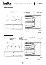
N.B. Ignition without gas pilot
burner only on TS 0 - 1 - 2
Connection to the feeding
circuit see BT 8910/2 and
BT 8911/1 for only one burner
Connection the feeding circuit
(see BT 8866/4 and BT 8868/2)
for more burner
Gas inlet
(Methane - L.P.G.) Max. pressure 300 mbar
for TS - GI 1000 / 500 mbar for PYR
PRINCIPLE DIAGRAM FOR HEAVY OIL TS - PYR - GI 1000 MAIN
PUSHING SYSTEM (DEGASSING - FILTERING - PUSHING AND HEATING)
Piping to be made by the installer
Heating and thermic insulation
Summary of Contents for TS 0 GN
Page 2: ......
Page 47: ......
Page 48: ......
Page 49: ......
Page 50: ......
Page 51: ......
Page 52: ......
Page 53: ......
Page 54: ......
Page 55: ......
Page 56: ......
Page 57: ......
Page 58: ......
Page 59: ......
Page 60: ......
Page 61: ......
Page 62: ......
Page 63: ......
Page 64: ......
Page 65: ......
Page 66: ......
Page 67: ......
Page 68: ......
Page 69: ......
Page 70: ......
Page 71: ......
Page 72: ......
Page 73: ......
Page 74: ......
Page 75: ......
Page 76: ......
Page 77: ......
Page 78: ......
Page 79: ......
Page 80: ......
Page 81: ......
Page 82: ......
Page 83: ......
Page 84: ......
Page 85: ......
Page 86: ......
Page 87: ......
Page 88: ......
Page 89: ......
Page 90: ......
Page 91: ......
Page 92: ......
Page 93: ......
Page 94: ......
Page 95: ......


