


E
N
G
L
I
S
H
7 / 18
0006081362_200906
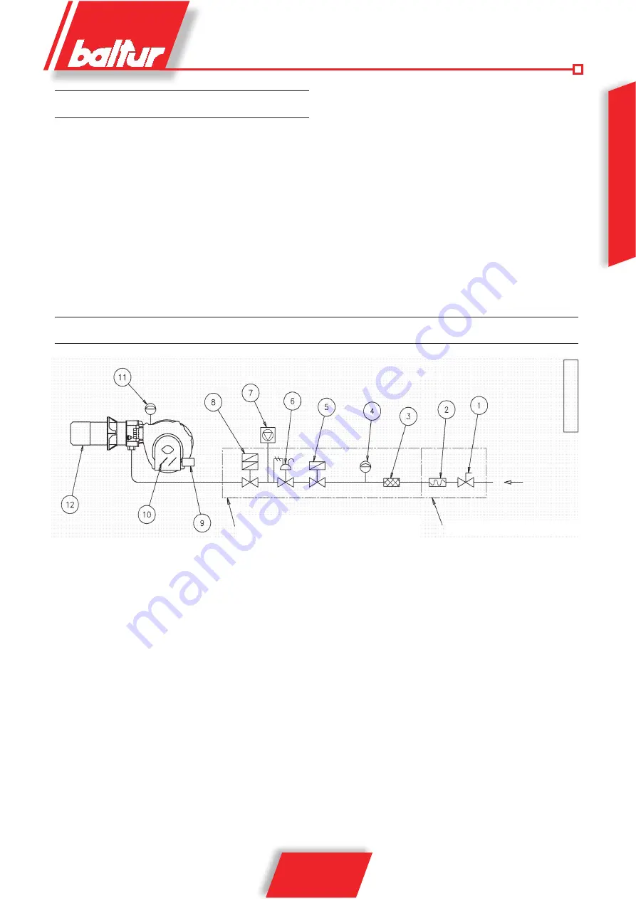
Legend
1) Manual shut off valve
2) Anti-vibration joint
3) Gas filter
4) Minimum gas pressure switch
5) Safety valve
6) Pressure regulator
Gas train
supplied by the manufacturer
The job of the installer
POWER SUPPLY LINE
The gas supply scheme is shown in the diagram below. The gas
train is certified in accordance with regulations EN 676 and is sup
-
plied separately from the burner.
A manual shut off valve and anti-vibration joint must be installed
upstream of the gas valve, as shown in the diagram.
In the case of a gas train with a pressure regulator that is not incor
-
porated in a monoblock valve,
we consider it useful to give the following practical advice regar
-
ding the installation of accessory components to the gas piping
close to the burner:
1) To prevent severe drops in pres-sure on ignition it is advisble
to have a length of piping of 1.5 to 2 metres between the point
of application of the stabiliser or pressure reducer and the
burner. This pipe must have a diameter equal to or greater
than the connector to the burner.
2) For the better working of the pressure regulator it is advisable
to apply it to the horizontal piping, after the filter. The gas pres
-
sure regulator must be adjusted when working at maximum
capacity and actually used by the burner. The delivery pres
-
sure must be adjusted to a level slightly below the maximum
obtainable. (that which is obtained when the regulation screw
is turned almost to the end); in the specific case, when the
regulation screw is tightened, the output pressure from the
regulator increases and when it is loosened it decreases.
GENERAL GAS BURNER SYSTEM
7) Valves seal control device (obligatory for burner with maxi
-
mum nominal thermal out-put over 1200 kW)
8) Two-stage working valve
9) Control servomotor
10) Air adjustment gate
11) Air pressure switch
12) Combustion head
N° 0002910950n1
Summary of Contents for TBG 45
Page 2: ......
Page 4: ......
Page 5: ...0006081362_200906...
Page 6: ......
Page 80: ...2 18 0006081362_200906 BALTUR a b c a b c d e f g...
Page 81: ...3 18 0006081362_200906 2 RC a b c d e a b a b c d...
Page 84: ...6 18 0006081362_200906 TBG 45P 60P TBG 45 60 EN 676...
Page 85: ...7 18 0006081362_200906 N 0002910950n1 1 2 3 4 5 6 7 1200 8 2 9 10 11 12 EN 676 1 1 5 2 2...
Page 86: ...8 18 0006081362_200906 3 6 5 4 7 8 8a 9 9...
Page 91: ...13 18 0006081362_200906 4 5 12 13 CO2 10 O2 3 CO 0 1 14 921 15 16 30 31 3 30 31 17 30 31...
Page 92: ...14 18 0006081362_200906 0002935680 A B C TBG 45 45P 4 5 4 TBG 60P 4 10 TBG 60 4 11 4 1 2 3 4 5...
Page 98: ...2 18 0006081362_200906 a b c a b c d e f g...
Page 99: ...3 18 0006081362_200906 2 RC a b c d a b c d e a b a b c d...
Page 102: ...6 18 0006081362_200906 LPG TBG 45 60 TBG 45P 60P LPG EN267...
Page 103: ...7 18 0006081362_200906 EN676 1 1 5m 2m 2 1 2 3 4 5 6 7 1200kW 8 9 10 11 12...
Page 104: ...8 18 0006081362_200906 3 1 2 6 5 7 4 1 8 8A 9 8 9 17...
Page 107: ...11 18 0006081362_200906 LED tw LME21 10 AL 10 AL 1 3...
Page 109: ...13 18 0006081362_200906 15 16 30 31 30 31 17 30 31...
Page 110: ...14 18 0006081362_200906 A B C TBG 45 45P 4 5 4 TBG 60P 4 10 TBG 60 4 11 4 1 2 3 4 5...
Page 112: ...16 18 0006081362_200906 1 1 2 Fig 1 2 3 4 5 Fig 2 3 6 7 8 8 Fig 3 4 9 10 Fig 4...
Page 114: ...18 18 0006081362_200906 230V 230V 14...
Page 115: ...115 122 00060811362_200906 3 A RU LGB 21 L1 N...
Page 116: ...116 122 00060811362_200906 3 A RU LGB 21 L1 N...
Page 117: ...117 122 00060811362_200906 3 A RU L1 N...
Page 118: ...118 122 00060811362_200906 3 A RU TR SARI YE L MAV KAHV RE NG S YAH NOLU S YAH KABL0 L1 N...
Page 121: ......