


ENGLISH
15 / 34
0006160178_201711
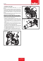
DESCRIPTION OF TBG 45P - 60P OPERATION
When the main switch and the I/O switch START/STOP switch on
the electrical panel are turned on, if the thermostats are on, voltage
reaches the command and control device, which starts up the burner
(LED 7 comes on).
This turns on the fan motor for pre-ventilation of the combustion
chamber. At the same time, the servomotor commanding the air
shutter opens in the position corresponding to the second flame, so
pre-ventilation takes place with the air shutter in the second flame
position.
At the end of the pre-ventilation phase, the air shutter is returned to
the first flame position, then the ignition transformer comes on and, 2
seconds later, the gas valves open.
The main valve, which has two stages, has a device for adjusting gas
delivery for the first and second flame.
The air shutter is operated by an electric servomotor(see
SERVOMOTOR CAM ADJUSTMENT).Keep in mind that when
the burner is locked out because the thermostat has tripped, the
servomotor returns the air shutter to the closed position.The presence
of the flame, detected by the control device, permits continuation and
completion of ignition, turning off the ignition transformer. The second
flame then comes on (combustion air is increased and the second
stage of the main valve opens).
If there is no flame, the appliance shuts down in "safety lock-out"
mode (LED 8 comes on) within 3 seconds of the opening of the first
flame on the main valve.
In “safety lock-out” mode the valves are closed again immediately.
To reset the appliance from safety lock-out mode, press button Reset
button on the electrical panel.
0002935620
2
8
7
1
5
10
6
9
4
3
Summary of Contents for TBG 45 P
Page 2: ......
Page 34: ...ITALIANO 32 34 0006160178_201711 SCHEMI ELETTRICI ...
Page 35: ...ITALIANO 33 34 0006160178_201711 ...
Page 68: ...ENGLISH 32 34 0006160178_201711 WIRING DIAGRAMS ...
Page 69: ...ENGLISH 33 34 0006160178_201711 ...
Page 71: ......