background image

ITALIANO

31 / 34

0006160178_201711

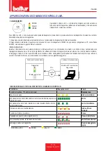
ISTRUZIONI PER L'ACCERTAMENTO DELLE CAUSE DI IRREGOLARITÀ NEL 

FUNZIONAMENTO E LA LORO ELIMINAZIONE

IRREGOLARITÁ

L'apparecchio  va  in  "blocco" 

con  fiamma  (lampada  rossa 

accesa).Guasto circoscritto al 

dispositivo di controllo fiamma.

L'apparecchio va in "blocco", il gas 

esce, ma la fiamma non è presente 

(lampada rossa accesa).Guasto 

circoscritto al circuito di accensione.

L'apparecchio va in "blocco", il gas 

esce, ma la fiamma non è presente 

(lampada rossa accesa).

POSSIBILE CAUSA

Disturbo della corrente di ionizzazione 

da parte del trasformatore di 

accensione.

Sensore fiamma (sonda ionizzazione) 

inefficiente.

Sensore di fiamma (sonda 

ionizzazione) in posizione non 

corretta.

Sonda ionizzazione o relativo cavo a 

massa.

Collegamento elettrico interrotto del 

sensore di fiamma.

Tiraggio inefficiente o percorso fumi 

ostruito.

Disco fiamma o testa di combustione 

sporchi o logori.

Apparecchiatura guasta.

Manca ionizzazione.

Guasto nel circuito di accensione.

Cavetto trasformatore d'accensione 

scarica massa.

Cavetto d'accensione scollegato.

Trasformatore d'accensione guasto.

La distanza tra l'elettrodo e massa 

non è corretta.

Isolatore sporco e quindi l'elettrodo 

scarica massa.

Rapporto aria/gas non corretto.

La tubazione del gas non è stata 

adeguatamente sfogata dall'aria 

(caso di prima accensione).

La pressione del gas è insufficiente o 

eccessiva.

Passaggio aria tra disco e testa 

troppo chiuso.

RIMEDIO

Invertire l'alimentazione (lato 230V) del 

trasformatore di accensione e verificare 

con micro-amperometro analogico.

Sostituire il sensore fiamma.

Correggere la posizione del sensore 

di fiamma e, successivamente, 

verificarne l'efficienza inserendo il micro-

amperometro analogico.

Verificare visivamente e con strumento.

Ripristinare il collegamento.

Controllare che i passaggi fumo caldaia/

raccordo camino siano liberi.

Verificare visivamente ed eventualmente 

sostituire.

8 Sostituirla.

Se la "massa" dell'apparecchiatura non 

è efficiente non si verifica la corrente 

di ionizzazione.Verificare l'efficienza 

della "massa" all'apposito morsetto 

dell'apparecchiatura e al collegamento a 

"terra" dell'impianto elettrico.

Verificare l'alimentazione del trasformatore 

d'accensione (lato 230V) e circuito alta 

tensione (elettrodo a massa o isolatore 

rotto sotto il morsetto di bloccaggio).

2 Sostituirlo.

3 Collegarlo.

4 Sostituirlo.

Metterlo alla corretta distanza.

Pulire o sostituire l'isolatore e l'elettrodo.

Correggere il rapporto aria/gas 

(probabilmente c'è troppa aria o poco 

gas).

Sfogare ulteriormente, con le dovute 

cautele, la tubazione del gas.

Verificare il valore della pressione gas 

al momento dell'accensione (usare 

manometro ad acqua, se possibile).

Adeguare l'apertura disco/testa.

Summary of Contents for TBG 45 P

Page 1: ...STAGE GAS BURNERS ITALIANO Manuale istruzioni per l installazione l uso e la manutenzione IT Installation use and maintenance instruction manuale EN TBG 45 P TBG 60P ISTRUZIONI ORIGINALI IT ORIGINAL INSTRUCTIONS IT 0006160178_201711 ...

Page 2: ......

Page 3: ...45P 60P 15 Accensione e regolazione gas metano 16 Misurazione della corrente di ionizzazione 18 Apparecchiatura di comando e controllo LME 19 Schema di regolazione distanza disco elettrodi 22 Regolazione dell aria sulla testa di combustione 22 Manutenzione 24 Bruciatore di gas a due stadi 25 tempi di manutenzione 26 Vita attesa 27 Precisazioni sull uso del propano 28 Schema di principio per riduzi...

Page 4: ...rk Sparkgas TBG TBL TS IBR IB Variante LX per basse emissioni NOx rispettano i requisiti minimi imposti dalle Direttive Europee 2009 142 CE D A G 2014 30 CE C E M 2014 35 CE D B T 2006 42 CE D M e sono conformi alle Norme Europee prEN 676 2008 gas e misti lato gas prEN 267 2008 gasolio e misti lato gasolio EN 60335 1 2012 01 EC 2014 01 tutti i bruciatori EN 60335 2 102 EN 60204 1 Cento 8 Maggio 20...

Page 5: ...ione dell apparecchio mese anno sono indicati sulla targa identificazione bruciatore presente sull apparecchio L apparecchio non è adatto a essere usato da persone bambini compresi le cui capacità fisiche sensoriali o mentali siano ridotte oppure con mancanza di esperienza o di conoscenza l uso dell apparecchio è consentito a tali persone solo nel caso in cui possano beneficiare attraverso l inter...

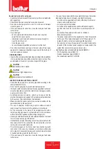
Page 6: ...lla loro sede Rendere innocue quelle parti che potrebbero essere potenziali fonti di pericolo AVVERTENZE PER L AVVIAMENTO IL COLLAUDO L USO E LA MANUTENZIONE L avviamento il collaudo e la manutenzione devono essere effettuati esclusivamente da personale professionalmente qualificato in ottemperanza alle disposizioni vigenti Fissato il bruciatore al generatore di calore accertarsi durante il collau...

Page 7: ...avi dell impianto sia idonea alla potenza assorbita dall apparecchio Non é consentito l uso di adattatori prese multiple e o prolunghe per l alimentazione generale dell apparecchio alla rete elettrica Prevedere un interruttore onnipolare con distanza d apertura dei contatti uguale o superiore a 3 mm per l allacciamento alla rete elettrica come previsto dalle normative di sicurezza vigenti condizio...

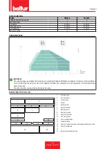
Page 8: ...HIATURA LME22 LME22 REGOLAZIONE PORTATAARIA servomotore elettrico servomotore elettrico PRESSIONE SONORA dBA 76 76 POTENZA SONORA dBA 88 88 PESO CON IMBALLO kg 40 42 PESO SENZA IMBALLO kg 32 34 Potere calorifico inferiore alle condizioni di riferimento 15 C 1013 hPa mbar Gas metano Hi 9 45 kWh Stm 34 02 MJ Stm Propano Hi 24 44 kWh Stm 88 00 MJ Stm Per tipi di gas e pressioni diverse consultare i n...

Page 9: ...accoppiamenti bruciatore caldaia Per il corretto funzionamento del bruciatore le dimensioni della camera di combustione devono essere rispondenti alla normativa vigente in caso contrario vanno consultati i costruttori Il bruciatore non deve operare al di fuori del campo di lavoro dato TARGA IDENTIFICAZIONE BRUCIATORE 1 2 3 4 5 6 7 11 14 12 Targa_descr_bru 8 9 10 13 16 15 1 Logo aziendale 2 Ragione...

Page 10: ...po di gas Indice di Wobbe inferiore Potere calorifico inferiore Portata gas Stm3 h Portata min gas Stm h Portata max gas Stm h Potenza min gas kW potenza max gas kW Pressione gas di rete hPa mbar Pressione gas a valle dello stabilizzatore hPa mbar CO CO2 temperatura fumi temperatura aria ...

Page 11: ...gas 7 Quadro elettrico 8 Motore 9 Servomotore regolazione aria 9a Regolazione aria manuale 10 Pressostato aria 11 Targa identificazione bruciatore 0002471170N1 10 9 9a 8 7 6 1 2 3 5 4 11 QUADRO ELETTRICO 1 Apparecchiatura 2 Trasformatore d accensione 3 Contattore motore 4 Connettore 7 poli 5 Connettore 4 poli 6 Pulsate di sblocco 7 Zoccolo relè 8 Relè 9 Quadro elettrico 0002935620 2 8 7 1 5 10 6 9...

Page 12: ...B D E B6 0002471170N2 45 45 L N I I M Modello A A1 A2 B B1 B2 B6 C TBG 45 P 550 270 280 433 325 108 160 920 TBG 60P 550 270 280 455 325 130 160 880 Modello D E Ø F Ø I I1 LØ M N Ø TBG 45 P 140 300 137 133 215 215 200 245 M12 145 TBG 60P 140 300 156 152 260 260 225 300 M12 160 ...

Page 13: ... Per ottenere il miglior funzionamento del regolatore di pressione è opportuno che lo stesso sia applicato su tubazione orizzontale dopo il filtro Il regolatore di pressione del gas deve essere regolato mentre lavora alla massima portata effettivamente utilizzata dal bruciatore La pressione in uscita deve essere regolata ad un valore leggermente inferiore a quella massima realizzabile APPLICAZIONE...

Page 14: ...guendo le istruzioni riportate al paragrafo Manutenzione estrarre il gruppo miscelazione e togliere la vite 8 che collega l asta di avanzamento 14 del gruppo con il tubo mandata gas 15 Togliere la vite 16 che collega il miscelatore gas 17 al tubo Ruotare di 180 il raccordo a gomito 18 e il miscelatore 17 in modo che l ingresso sia rivolto verso l alto Fissare nuovamente al tubo mandata gas il misc...

Page 15: ...amento alla rete elettrica come previsto dalle normative di sicurezza vigenti Per i collegamenti elettrici linea e termostati vedere il relativo schema elettrico Sguainare l isolante esterno del cavo di alimentazione nella misura strettamente necessaria al collegamento evitando così che il filo possa venire a contatto con parti metalliche Per eseguire il collegamento del bruciatore alla linea di a...

Page 16: ...consentita esclusivamente a personale professionalmente qualificato In caso di reti elettriche a 230 V fase fase se queste sono sbilanciate la tensione fra elettrodo di rilevazione fiamma e massa può risultare insufficiente a garantire il corretto funzionamento del bruciatore L inconveniente è eliminato impiegando il trasformatore d isolamento tipo AR1 codice 0005020028 che va collegato come indic...

Page 17: ...ncipale a due stadi è provvista di dispositivo per regolare l erogazione di gas per la prima e la seconda fiamma La serranda dell aria è azionata da un apposito servomotore elettrico vedi REGOLAZIONE CAMME SERVOMOTORE Tenere presente che all arresto del bruciatore per intervento del termostato la serranda viene riportata dal servomotore nella posizione di chiusura La presenza della fiamma rilevata...

Page 18: ...zione occorre accertarsi che il pressostato di controllo della pressione dell aria effettui lo scambio da posizione di chiuso senza rilevamento di pressione deve passare nella posizione di chiuso con rilevamento di pressione dell aria Se il pressostato aria non rileva la pressione sufficiente non viene inserito il trasformatore di accensione e nemmeno le valvole del gas pertanto l apparecchiatura ...

Page 19: ... regolazione del pressostato ad un valore sufficiente per rilevare la pressione di aria esistente durante la fase di pre ventilazione Il pressostato di controllo della pressione del gas minima ha lo scopo di impedire il funzionamento del bruciatore quando la pressione del gas non risulta quella prevista Dalla funzione specifica del pressostato risulta evidente che il pressostato di controllo della...

Page 20: ...e il cui valore minimo per assicurare il funzionamento dell apparecchiatura è riportato nello schema elettrico specifico Terminata la misurazione ripristinare il ponticello in precedenza scollegato Lacorrenteminimadiionizzazioneperfarfunzionarel apparecchiatura è di 6 μA La fiamma del bruciatore genera una corrente nettamente superiore tale da non richiedere normalmente alcun controllo da parte de...

Page 21: ...iagnosi premere per almeno 3 secondi il pulsante di sblocco un lampeggio veloce di colore rosso indicherà che la funzione è attiva analogamente per disattivare la funzione basterà premere per almeno 3 secondi il pulsante di sblocco la commutazione verrà indicata con luce gialla lampeggiante EK xxxxxxxx xxxxxxxx xxxxxxxx xxxxxxxx xxxxxxxx xxxxxxxx 3 s 7101z03e0305 Posizione di funzionamento interfa...

Page 22: ...urezza TSA Malfunzionamento valvole combustibile Malfunzionamento rilevatore fiamma Difettosità nella taratura del bruciatore assenza di combustibile Mancata accensione difettosità trasformatore di accensione 3 lampeggi On Malfunzionalità pressostato aria LP Mancanza segnale pressostato dopo T10 Contatto del pressostato LP incollato in posizione di riposo 4 lampeggi On Luce estranea durante la fas...

Page 23: ...essostato gas H Interruttore principale HS Contatto ausiliario relè ION Sonda di Ionizzazione K1 4 Relè Interni KL Fiamma bassa LK Serranda dell Aria LKP Posizione della serranda dell aria LP Pressostato aria LR Modulazione M Motore ventola MS Motore sincrono NL Carico nominale NT Alimentatore elettrico QRA Rivelatore di Fiamma QRC Rivelatore di fiamma blu bl br marrone sw nero R Termostato presso...

Page 24: ...tima miscela e stabilità di fiamma Può essere indispensabile avere un elevata pressione d aria a monte del disco per evitare pulsazioni di fiamma questa condizione è praticamente indispensabile quando il bruciatore lavora su focolare pressurizzato e o ad alto carico termico Il dispositivo che chiude l aria sulla testa di combustione deve essere portato in una posizione tale da ottenere sempre diet...

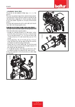
Page 25: ...e in funzione delle caratteristiche del focolare REGOLAZIONE CAMME SERVOMOTORE SQN72 XA4A20 PER TBG P 1 2 3 4 I Camma regolaizone aria 2 fiamma 80 II Chiusura totale bruciatore fermo 0 III Camma regolazione aria 1 fiamma 20 IV Camma inserzione valvola 2 fiamma 40 1 Perno inserzione ed esclusione accoppiamento motore albero camme 2 Camme regolabili 3 Scala di riferimento 4 Indicatore di posizione P...

Page 26: ...l seguente modo Svitare le viti di fissaggio 6 e rimuovere il coperchio 11 Assicurarsi che la piastrina mobile 23 sia tenuta bloccata dalla vite 8 Questo consentirà una volta terminate le operazioni di manutenzione di risistemare il gruppo miscelazione nella stessa posizione a cui era stato precedentemente regolato Svitare la vite 24 che fissa l asta di avanzamento del gruppo alla piastrina mobile...

Page 27: ...no ad una temperatura inferiore al punto di rugiada dando luogo a presenza di acqua di condensazione nel camino Quando il bruciatore a due fiamme è installato su una caldaia per la produzione di acqua calda ad uso riscaldamento deve essere collegato in modo da lavorare a regime con entrambe le fiamme arrestandosi completamente senza passaggio alla prima fiamma quando la temperatura prestabilita vi...

Page 28: ...CCANICA VERIFICA USURA E FUNZIONALITÁ INGRASSAGGIO PATTINO E VITI ANNO LEVE TIRANTI SNODI SFERICI CONTROLLO EVENTUALI USURE LUBRIFICAZIONE COMPONENTI ANNO IMPIANTO ELETTRICO VERIFICA CONNESSIONI E SERRAGGIO MORSETTI ANNO INVERTER PULIZIA VENTOLA DI RAFFREDDAMENTO E SERRAGGIO MORSETTI ANNO SONDA CO PULIZIA E CALIBRAZIONE ANNO SONDA O2 PULIZIA E CALIBRAZIONE ANNO LINEA COMBUSTIBILE FILTRO GAS SOSTIT...

Page 29: ...imento alla vita attesa di seguito indicata Per condizioni operative normali si intendono applicazioni su caldaie ad acqua e generatori di vapore oppure applicazioni industriali conformi alla norma EN 746 in ambienti con temperature nei limiti previsti dal presente manuale e con grado di inquinamento 2 conformemente all allegato M della norma EN 60335 1 Componente di sicurezza Vita attesa di proge...

Page 30: ...o funzionamento in sicurezza La gassificazione naturale da batteria di bombole o serbatoio è utilizzabile solo per impianti di piccola potenza La capacità di erogazione in fase di gas in funzione delle dimensioni del serbatoio e della temperatura minima esterna sono esposte solo a titolo indicativo nella seguente tabella Temperatura minima 15 C 10 C 5 C 0 C 5 C Serbatoio 990 l 1 6 Kg h 2 5 Kg h 3 ...

Page 31: ... del massimo richiesto dall utilizzatore Riduttore di 2 salto Uscita 30 hPa mbar Portata il doppio del massimo richiesto dall utilizzatore Filtro a Y Filtro Filtro Presa di pressione Riduttore di 2 salto Uscita 30 hPa mbar Portata il doppio del massimo richiesto dall utilizzatore Filtro a Y Rubinetto a sfera Giunto antivibrante Bruciatore Caldaia a pavimento o murale Raccordo FORNITO DAL COSTRUTTO...

Page 32: ...c 3 Posizionare le feritoie C a filo disco fiamma D come rappresentato in figura bloccare in modo adeguato le nuove riduzioni agendo sulle rispettive viti CAUTELA AVVERTENZE In alcune particolari applicazioni nel caso si verificassero pulsazioni di fiamma durante il funzionamento del bruciatore con gas naturale si consiglia di utilizzare le riduzioni previste per il combustibile GPL TBG 60 P 1 Dop...

Page 33: ... gas non è stata adeguatamente sfogata dall aria caso di prima accensione 3 La pressione del gas è insufficiente o eccessiva 4 Passaggio aria tra disco e testa troppo chiuso RIMEDIO 1 Invertire l alimentazione lato 230V del trasformatore di accensione e verificare con micro amperometro analogico 2 Sostituire il sensore fiamma 3 Correggere la posizione del sensore di fiamma e successivamente verifi...

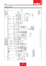
Page 34: ...ITALIANO 32 34 0006160178_201711 SCHEMI ELETTRICI ...

Page 35: ...ITALIANO 33 34 0006160178_201711 ...

Page 36: ... M PRESSOSTATO DI MASSIMA Pm PRESSOSTATO DI MINIMA S1 INTERRUTTORE MARCIAARRESTO S2 PULSANTE SBLOCCO SG INTERRUTTORE GENERALE T2 TERMOSTATO 2 STADIO TA TRASFORMATORE D ACCENSIONE TC TERMOSTATO CALDAIA TS TERMOSTATO DI SICUREZZA X1 MORSETTIERA BRUCIATORE X1B S CONNETTORE ALIMENTAZIONE X2B S CONNETTORE 2 STADIO X3 CONNETTORE Pm X4 CONNETTORE YP X9 CONNETTORE TRASFORMATORE Y1 Y2 ELETTROVALVOLE 1 2 ST...

Page 37: ...tion of TBG 45P 60P operation 15 Natural gas ignition and regulation 16 Ionisation current measurement 18 Control and command equipment LME 19 Diagram for the regulation of the electrode disk distance 22 Air regulation on the combustion head 22 Maintenance 24 Two stage gas burner 25 Maintenance time 26 Expected lifespan 27 Specifications for propane use 28 Diagram illustrating the principle of L P...

Page 38: ...iNOx Spark Sparkgas TBG TBL TS IBR IB Variant LX for low NOx emissions respect the minimal regulation of the European Directives 2009 142 CE D A G 2014 30 CE C E M 2014 35 CE D B T 2006 42 CE D M and compliant with the European Standards prEN 676 2008 gas and dual fuel gas side prEN 267 2008 diesel and dual fuel diesel side EN 60335 1 2012 01 EC 2014 01 all burners EN 60335 2 102 EN 60204 1 Cento ...

Page 39: ...C The storage time is 3 years GENERAL INSTRUCTIONS The equipment production date month year is written on the burner identification plate located on the equipment The device is not suitable to be used by persons including children with reduced physical sensory or mental capacities or lack of experience or knowledge such persons can use the device only if they can benefit through the intermediation...

Page 40: ...remove the control wheels from their position Render harmless any potentially dangerous parts INSTRUCTIONS FOR START UP INSPECTION USE AND MAINTENANCE Start up inspection and maintenance of the equipment must only be carried out by qualified technicians in compliance with current regulations Once you have fastened the burner to the power generator make sure that during testing the flame produced d...

Page 41: ...r absorbed by the equipment The use of adaptors multiple plugs and or extension leads to supply power from the mains to the appliance is not allowed For the connection to the mains fit an omnipolar switch with a contact opening gap equal to or greater than 3 mm in accordance with current safety regulations Overvoltage category III Use only double insulated cables with external thickness of at leas...

Page 42: ...ROBE EQUIPMENT LME22 LME22 AIRFLOW REGULATION electric servomotor electric servomotor SOUND PRESSURE dBA 76 76 SOUND POWER dBA 88 88 WEIGHT WITH PACKING kg 40 42 WEIGHT WITHOUT PACKING kg 32 34 Calorific power lower than reference conditions 15 C 1013 hPa mbar Natural gas Hi 9 45 kWh Stm 34 02 MJ Stm Propane gas Hi 24 44 kWh Stm 88 00 MJ Stm For different types of gas and pressure values please co...

Page 43: ...t boilers corresponding to Standard EN676 and are indicative of the burner boiler combination For correct working of the burner the size of the combustion chamber must correspond to current regulations if not the manufacturers must be consulted The burner should not work outside the indicated work range BURNER IDENTIFICATION PLATE 1 2 3 4 5 6 7 11 14 12 Targa_descr_bru 8 9 10 13 16 15 1 Company lo...

Page 44: ...ow Type of gas Lower Wobbe number Lower calorific power Gas flow Stm3 h Min gas flow rate Stm h Max gas flow rate Stm h Min gas power kW Max gas power kW Network gas pressure hPa mbar Gas pressure downstream of the stabiliser hPa mbar CO CO2 fume temperature air temperature ...

Page 45: ...lange 7 Electrical panel 8 Motor 9 Air regulation servomotor 9a Manual air regulation system 10 Air pressure switch 11 Burner identification plate 0002471170N1 10 9 9a 8 7 6 1 2 3 5 4 11 ELECTRICAL PANEL 1 Control box 2 Ignition transformer 3 Motor contactor 4 7 pole connector 5 4 pole connector 6 Reset button 7 Relay base 8 Relay 9 Electrical panel 0002935620 2 8 7 1 5 10 6 9 4 3 ...

Page 46: ...B D E B6 0002471170N2 45 45 L N I I M Model A A1 A2 B B1 B2 B6 C TBG 45 P 550 270 280 433 325 108 160 920 TBG 60P 550 270 280 455 325 130 160 880 Model D E Ø F Ø I I LØ M N Ø TBG 45 P 140 300 137 133 215 215 200 245 M12 145 TBG 60P 140 300 156 152 260 260 225 300 M12 160 ...

Page 47: ...r To ensure optimal operation of the pressure regulator it should be applied to the horizontal pipe after the filter The gas pressure regulator must be adjusted when it is working at the maximum output actually used by the burner The delivery pressure must be adjusted to a level slightly below the maximum obtainable BURNER CONNECTION TO THE BOILER ASSEMBLING THE HEAD UNIT Position insulating seal ...

Page 48: ...cedure Following the instructions detailed in the Maintenance section extract the mixer unit and remove the screw 8 which connects the unit s forward movement rod 14 to the gas delivery pipe 15 Remove the screw 16 which connects the gas mixer 17 to the pipe Turn the elbow fitting 18 by 180 and the gas mixer 17 in such a way that the inlet gas is facing upwards Fix again the mixer and unit forward ...

Page 49: ...ater than 3 mm in accordance with current safety regulations Refer to the wiring diagram for electrical connections line and thermostats Unsheathe the external insulating cover of the power cable to the necessary extent for the connection thus avoiding the wire from coming into contact with metal parts To carry out the connection of the burner to the power supply line proceed as follows Remove the...

Page 50: ...ed to open the burner electrical panel In case of unbalanced 230V phase phase mains supply systems the voltage between the flame detector electrode and earth might not be enough to ensure the correct operation of the burner The problem is eliminated using the isolation transformer type AR1 code 0005020028 which must be connected as shown in the following diagram The electric motor is equipped with...

Page 51: ...e main valve which has two stages has a device for adjusting gas delivery for the first and second flame The air shutter is operated by an electric servomotor see SERVOMOTOR CAM ADJUSTMENT Keep in mind that when the burner is locked out because the thermostat has tripped the servomotor returns the air shutter to the closed position The presence of the flame detected by the control device permits c...

Page 52: ...cription During pre ventilation make sure that the air pressure control switch changes its status from the closed position without pressure measurement to the closed position with pressure measurement If the air pressure switch does not detect sufficient pressure the ignition transformer is not switched on nor are the gas valves and so the equipment is stopped in lock out mode On first switching o...

Page 53: ... sufficient level to detect the existing air pressure during the pre ventilation stage The gas control pressure switch minimum prevents burner operation when gas pressure is not the foreseen one It is clear from the specific function of the pressure switches that the control pressure switch for minimum pressure must make use of the contact that is closed when the pressure switch detects pressure g...

Page 54: ...asure the ionisation current the minimum value of which is shown in the specific wiring diagram to ensure the operation of the equipment At the end of the measurement connect the jumper that has been disconnected The minimum ionisation current needed to run the equipment is 6 µA The burner flame generates a significantly higher current which usually does not require any control by the equipment Sh...

Page 55: ...on hold the reset button down for at least 3 seconds A quick red flashing indicates that the function is active Likewise hold the reset button down for at least 3 seconds to deactivate the function the switching will be indicated with a flashing yellow light EK xxxxxxxx xxxxxxxx xxxxxxxx xxxxxxxx xxxxxxxx xxxxxxxx 3 s 7101z03e0305 Operating position PC interface diagnostic analyser Colour code tab...

Page 56: ...es 2 blinks On No flame at the end of the safe ignition time TSA Faulty or soiled fuel valves Faulty or soiled flame detector Poor adjustment of burner no fuel No ignition Faulty ignition transformer 3 blinks On Defective LP air pressure switch No or faulty air pressure signal after completion t10 LP pressure switch contact welded in standby position 4 blinks On Extraneous light during the ignitio...

Page 57: ...s pressure switch H Main switch HS Auxiliary contactor relay ION Ionisation probe K1 4 Internal Relays KL Low flame LK Air damper LKP Air damper position LP Air pressure switch LR Modulation M Fan motor MS Synchronous motor NL Rated load NT Electric power supply QRA Flame Detection QRC Blue flame detector bl blue br brown sw black R Control thermostat pressure switch RV Gas adjustment device SA SQ...

Page 58: ... therefore an excellent mixture and flame stability High air pressure upstream of the disc may be necessary to prevent flame fluctuations this is particularly essential when the burner works on the combustion chamber that is pressurised and or at a high thermal load The device closing the air on the combustion head must be set to such position as to always obtain behind the disc a very high air pr...

Page 59: ...ecombustion head according to the characteristics of the furnace ADJUSTMENT OF SERVOMOTOR CAMS SQN72 XA4A20 FOR TBG P 1 2 3 4 I 1st flame air regulation cam 80 II Total air closure Burner stopped 0 III 1st flame air regulation cam 20 IV 2nd flame valve control cam 40 1 Camshaft motor coupling insertion and exclusion pin 2 Adjustable camshaft 3 Reference scale 4 Position indicator To adjust the set...

Page 60: ...ews 6 and remove the cover 11 Makes sure that the moveable plate 23 is maintained secured by the screw 8 Once the maintenance operations have been completed this will make it possible to return the mixer unit to the same position it was in last time it was adjusted Loosen the screw 24 which anchors the unit s forward movement rod to the mobile plate After having loosened the nut 9 remove the locki...

Page 61: ...ed and so fumes come out at a temperature lower than the dew point giving rise to the presence of condensation water in the flue When the two flame burner is installed on a hot water boiler for heating use it must be connected so that it works normally with both flames stopping completely without passing to the first flame when the pre set temperature is reached For this type of operation the ther...

Page 62: ...D OPERATION GREASING OF SLIDING BLOCK AND SCREWS YEAR LEVERS TIE RODS BALL JOINTS CHECK OF ANY WEAR COMPONENT LUBRICATION YEAR ELECTRICAL SYSTEM CHECK OF CONNECTIONS AND TERMINAL TIGHTENING YEAR INVERTER COOLING FAN CLEANING AND TERMINAL TIGHTENING YEAR CO PROBE CLEANING AND CALIBRATION YEAR O2 PROBE CLEANING AND CALIBRATION YEAR FUEL LINE GAS FILTER REPLACE THE FILTER YEAR HYDRAULIC GAS SEALS CHE...

Page 63: ... notes if necessary are independent and do not refer to the expected lifespan stated below Normal operating conditions means applications on water boilers and steam generators or industrial applications compliant with the standard EN 746 in environments with temperatures within the limits provided for in this manual and with pollution degree 2 in compliance with annex M of the standard EN 60335 1 ...

Page 64: ...rformance of the LPG system to ensure correct and safe operation Natural gasification from a cylinder bank or tank can be used only for systems having low power The following table gives an approximate indication of the gas output capacity according to the tank size and minimum outdoor temperature Minimum temperature 15 C 10 C 5 C 0 C 5 C 990 l tank 1 6 Kg h 2 5 Kg h 3 5 Kg h 8 Kg h 10 Kg h 3000 l...

Page 65: ...low rate double the maximum required by the user 2nd step reducer Output 30 hPa mbar Flow rate double the maximum required by the user Y filter Filter Filter Pressure intake 2nd step reducer Output 30 hPa mbar Flow rate double the maximum required by the user Y filter Ball cock Vibration proof joint Burner Free standing or wall mounted boiler Fitting SUPPLIED BY THE CUSTOMER RESPONSIBILITY OF THE ...

Page 66: ...art of the mixer 0002935830c 3 Position the holes C flush with the flame disc D as shown in the figure suitably secure the new reducers using the corresponding screws CAUTION WARNING In some particular applications in the event that there are pulsations in the flame during the operation of the burner with natural gas it is advisable to use the intended reducers for LPG fuel TBG 60 P 1 After loosen...

Page 67: ...irst ignition 3 The gas pressure is insufficient or excessive 4 Air flow between disc and head too narrow REMEDY 1 Invert the ignition transformer power supply 230V side and check using an analogue micro ammeter 2 Replace flame sensor 3 Correct the position of the flame sensor and then check for its efficiency by connecting the analogue micro ammeter 4 Check visually and using the instrument 5 Res...

Page 68: ...ENGLISH 32 34 0006160178_201711 WIRING DIAGRAMS ...

Page 69: ...ENGLISH 33 34 0006160178_201711 ...

Page 70: ... PA AIR PRESSURE SWITCH P M MAXIMUM PRESSURE SWITCH Pm MINIMUM PRESSURE SWITCH S1 START STOP SWITCH S2 RELEASE BUTTON SG MAIN SWITCH T2 2ND STAGE THERMOSTAT TA IGNITION TRANSFORMER TC BOILER THERMOSTAT TS SAFETY THERMOSTAT X1 BURNER TERMINAL BOARD X1B S POWER SUPPLY CONNECTOR X2B S 2nd STAGE CONNECTOR X3 Pm CONNECTOR X4 YP CONNECTOR X9 TRANSFORMER CONNECTOR Y1 Y2 1st 2nd STAGE SOLENOID VALVES Y10 ...

Page 71: ......
Page 72: ...t Il presente catalogo riveste carattere puramente indicativo La casa pertanto si riserva ogni possibilità di modifica dei dati tecnici e di quant altro in esso riportato Information contained in this catalogue is not binding The manufacturer reserves the right to change the technical data and any other data it contains ...

Reviews: