ENGLISH
12 / 34
0006160178_201711
ASSEMBLING THE GAS TRAIN
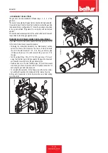
The gas train can be assembled in different ways: -1, -2, -3 , of the
gas train.
The burner is supplied by the gas train connection facing downward.
If you wish to invert the direction of train entrance to allow the gas train
to be assembled in configuration (1), follow the procedure described
in the section entitled: "Preparation for connection with train turned
upward".
Choose the most rational position for the set-up of the boiler room and
the position in which the gas pipeline arrives.
PREPARATION FOR TRAIN CONNECTION FACING UPWARD
If you wish to turn the train inlet upwards, before applying the burner
to the boiler, follow the subsequent procedure.
• Following the instructions detailed in the “Maintenance” section,
extract the mixer unit and remove the screw -8 which connects
the unit’s forward movement rod -14 to the gas delivery pipe
-15.Remove the screw -16 which connects the gas mixer -17 to
the pipe.
• Turn the elbow fitting -18 by 180° and the gas mixer -17 in such
a way that the inlet gas is facing upwards.Fix again the mixer and
unit forward movement rod to the gas delivery pipe.
• Remove the 4 nuts -19, slide the flame pipe -20 out of the relevant
stud bolts, put it back in position with the threaded connection for
anchoring the gas train turned upward.
• To complete the operation, fix the flame pipe to the burner screw-
nut and finally reposition the mixing unit in the relative housing.
At this point it is possible to fix the burner with a valve train looking
up on the boiler.
0002936660
1
2
3
16
17
0002936600
15
14
18
8
19
20
0002936610
Summary of Contents for TBG 45 P
Page 2: ......
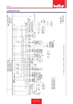
Page 34: ...ITALIANO 32 34 0006160178_201711 SCHEMI ELETTRICI ...
Page 35: ...ITALIANO 33 34 0006160178_201711 ...
Page 68: ...ENGLISH 32 34 0006160178_201711 WIRING DIAGRAMS ...
Page 69: ...ENGLISH 33 34 0006160178_201711 ...
Page 71: ......

