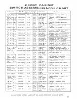
SHUTTER MOTOR & SVVITCHES
Switch/Coil
Part No.
Location on
Wire
Wire Color
Function
Diag-ram
No.
CAM #5
ASW-C3-8
B-16
53-5
White-Yellow
When Shutter is closed, completes
A.
T.
10-10
Red
start re. circuit to shutter motor,
48-13 Green-Black·
when shutter is open, completes start
re. circuit to timer cams Index Coil
Cam
#5
ASW-C2-15
D-27
31-4
Yellow-Red
When shutter is open, completes lock-
B.
N.C.
90-9
Grev
in circuit to lifter start re.
Cam
#5
ASW-C2-2
L-21
80-11
Black
When shutter is open, completes horn-
c.
N.C.
38-9
Yellow-Black
ing circuit to corner replay counter
steo up.
CAM #6
ASW-Cl0-5
E-26
74-11 Orange-Green
When shutter opens, pulses timer
A.
N.O.
30
Yellow
reset coil.
Cam
#6
ASW-Cl0-1
C-32
78-3
Orange-Black
When shutter opens, pulses Red, Yel-
B.
N.O.
30
Yellow
low Blue score unit resets also pulses
coin counter reset and scrambler step
uo.
Cam #6
ASW-Cl0-1
C-5
90-10
Grey
When shutter opens, pulses trip bank
c.
N.O.
30
Yellow
reset motor.
BALL LIFT
E-119-339
A-29
70
Orange
Energized thru Lifter start re. sw.
Motor
38-3
Yellow-Black
& ball lift re. sw. if 4th ball isn't
raised or timer has stepped at least
once.
Cam #1
ASW-ClX
C-29
91-1
Grey-Red
Completed ball lifter motor carryover
A.
N.O.
30
Yellow
circuit.
Cam #1
ASW-C2-15
0-4
85-6
Black-White
Opens Circuit to B-4 and B-5 Trip
B.
N.C.
65-13
Brown-White
Relays during ball lift cycle.
Cam
#1
ASW-C2-2
C-25
74-11
Orange-Green
Opens Timer Reset Circuit durmg
c.
N.C.
98-9
Grey-Black
Ball Lift Cycle.
Cam
#2
ASW-ClX
D-23
27-2
Blue-Orange
Completes Timer Unit Step-Up Cir-
A.
N.O.
43-2
Green-Yellow
cuit (1st thru 5th Step).
SHUTTER SWS.
ASW-Cl-29
D-14
91-13
Grey-Red
Completes Circuit to Coin Lockout
A.
N.C.
98-6
Grev-Black
Coil when Shutter is Closed.
Shutter
Sws.
ASW-Cl-29
C-13
51-8
White-Red
When Shutter is closed, completes
B.
N.C.
61-8
Brown-Red
circuit to start re. coil ready for
coinine: oulse.
Shutter Sws.
ASW-Clll-3
0-10
21-3
Blue-Red
When shutter is open completes cir-
c.
c.w.o.
0-11
27-15
Blue-Orange
cuit to Magic Sq. Index "E" coil until
"E" is homed.
0-10
83-11
Black-Yellow
Same as above for "B"
0-11
57-14
White -Orange
Same. as above for "C"
0-10
40-13
Green
Same as above for "D"
0-11
58-3
White-Black
Same as above for "E"
BALL GATE
ASW-A2-71
D-27
36
Yellow-Brown
Opens Circuit to Lifter Start Re.
N.C.
31-4
Yellow-Red
BALL RUNWAY
ASW-Al-30
D-28
38-8
Yellow-Black
Completes Lifter start re. Sw.
N.O.
30
Yellow
LIFTER ST ART
G-32-2500
A-27
70
Orange
Energized thru ball runway sw.
Re.
38J
Yellow-Black
A.
N.O.
ASW-Rl-8
C-27
36
Yellow-Brown
Completes lifter start re. Lock in
38-8
Yellow-Black
Circuit.
B.
N.C.
ASW-R2-5
P-4
65-13
Brown-White
Opens Circuit to B-4 & B-5 Trip Re.
15-11
Red-White
c.
N.C.
ASW-R2-5
E-29
31-3
Yellow-Red
Opens Circuit to Ball Lifter Motor.
21-3
Blue-Red
ALWAYS GIVE MODEL ANO PART NO. WHEN ORDERING SERVICE PARTS
36


