CORNER REPLAY COUNTER
Note #2: Magnet Assembly Adjustment
(1) Loosen both Screws (M)
(2) Loosen Lock Nut (A)
(3) Adjust the Height of the Magnet Assy. so that upon
the Stepping of the Pawl into the Tooth of the ratch
et, approximately 1/32 spacing will be visible be
tween the Pawl and the Ratchet Tooth as shown for
(G). If done properly, approximately 1/64 free
play cff the Pawl at rest in the Ratchet Tooth will
be visible when the Ratchet is mov ed by hand.
(4) Tighten the Screws (H)
(5) Slide the Stop (1) to rest against the Pawl (do not
force). The Pawl should rest against the Stop
and Ratchet only.
(6) Tighten Lock Screw (B}
(7) Tighten Lock Nut (A)
(8) Step Up the Magnet Assy. electrically and check
to see that the Stepping is all the way into each
tooth without missing any steps.
(9) Recheck all adjustments and re-adjust if necessary.
Recheck all adjustments
play of the Pawl at rest in the Ratchet Tooth will
be visible when the ratchet is moved by Hand.
Note #3: Step Adjustment
(1) Loosen all the Screws at
(L) (Q} (M)
and (P).
(2) Pull back the Switch (J) and Switch Bracket (0)
affthe way away from the Ratchet Assy., and
tighten down the Screws (M).
(3) While holding the Armature down to the Coil (D),
spin the Ratchet so that the Switch Roller (J) will
be in the Cam Slot, or near as possible to the
Cam Slot.
(4) Move back the Switch (J) or Switch Bracket (0)
toward the Ratchet (if need be) so that the Switch
Rqller (J) will just barely drop into the Cam Slot
(but cleanly), and tighten down the Screws (P).
(5) Adjust the Switch (J) (See Note #4).
(6) Step the Ratchet 25 Steps.
(7) Push the Switch (K) and Switch Bracket (N) all
the way toward the Ratchet Assy. , and tighten
down the Screws (L).
(8) Move the Switch (K) or Switch Bracket (N) (if need
be) so that the Switch Roller (K) will just barely
(but cleanly) drop into the Cam Slot, and tighten
down the Screws
(Q).
(9) Adjust the Switch
(K)
(See Note
#4).
(10) Re-check all adjustments.
Note #4: Switch Adjustment
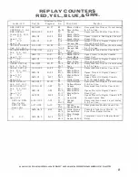
Switch/Coil
CORNER REPLAY
Cntr.
S. U. Coil
HOMING CAM
Sw.
N.O.
OPEN@ 25
(1) The lower switch leaf rollers must make at the
bottom of the Cam Slot, and on the outer Cam
edge without excess bowing of the Switch Leaf,
and with the Cam at the Center of the Leaf Rollers.
(2) The Switch Lifter must ride on the Lower Switch
Leaf at all times without excess bowing of the
Switch Leaf.
(3) All All
(3) All Switches must make on the 3rd or 4th Step
from the Starting Point in the Cam Slot.
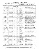
Location on
Wire
Part No.
Diagram
No.
Wire Color
Function
EA-30-1150
J-19
70
Orange
Energized thru Winner Circuit during
27-17
Blue-Orange
Corner Winner.
ASW-Cl-6
L-20
27-17
Blue-Orange
Completes Circuit to 16 Pulse Reset
80-11
Black
ASW-Cl-6
P-19
15-5
Red-White
Completes Circuit to Search Disc
21-8
Blue-Red
through CO-1 or CO-2 Trip Sws.
ALWAYS GIVE MODEL ANO PART NO. WHEN ORDERING SERVICE PARTS
41


